Automatic Shutdown Triggered by Low Voltage
Low voltage of the power supply will trigger automatic shutdown of the module.
The module keeps monitoring the voltage at VBAT. When it is lower than 3.4 V, the module shuts
down automatically.
Power-On/Off Control
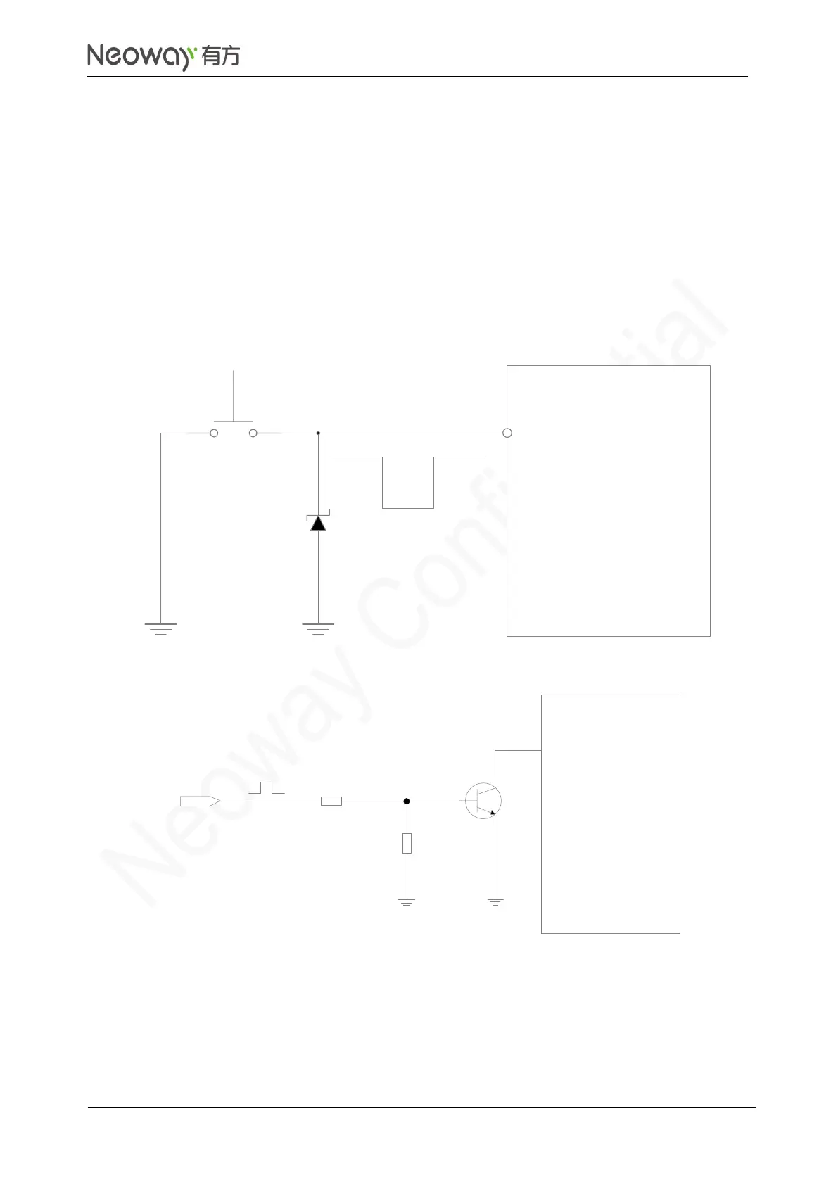
Figure 3-7 shows a reference circuit for ON/OFF control with inverted control logic.
Figure 3-7 Reference circuit for power-on/off control
In Figure 3-8, high level trigger power-ON state on the user side (USER_ON) after level shifting.
R1 and R2 can be adjusted according to the driving capability of the USER_ON pin.