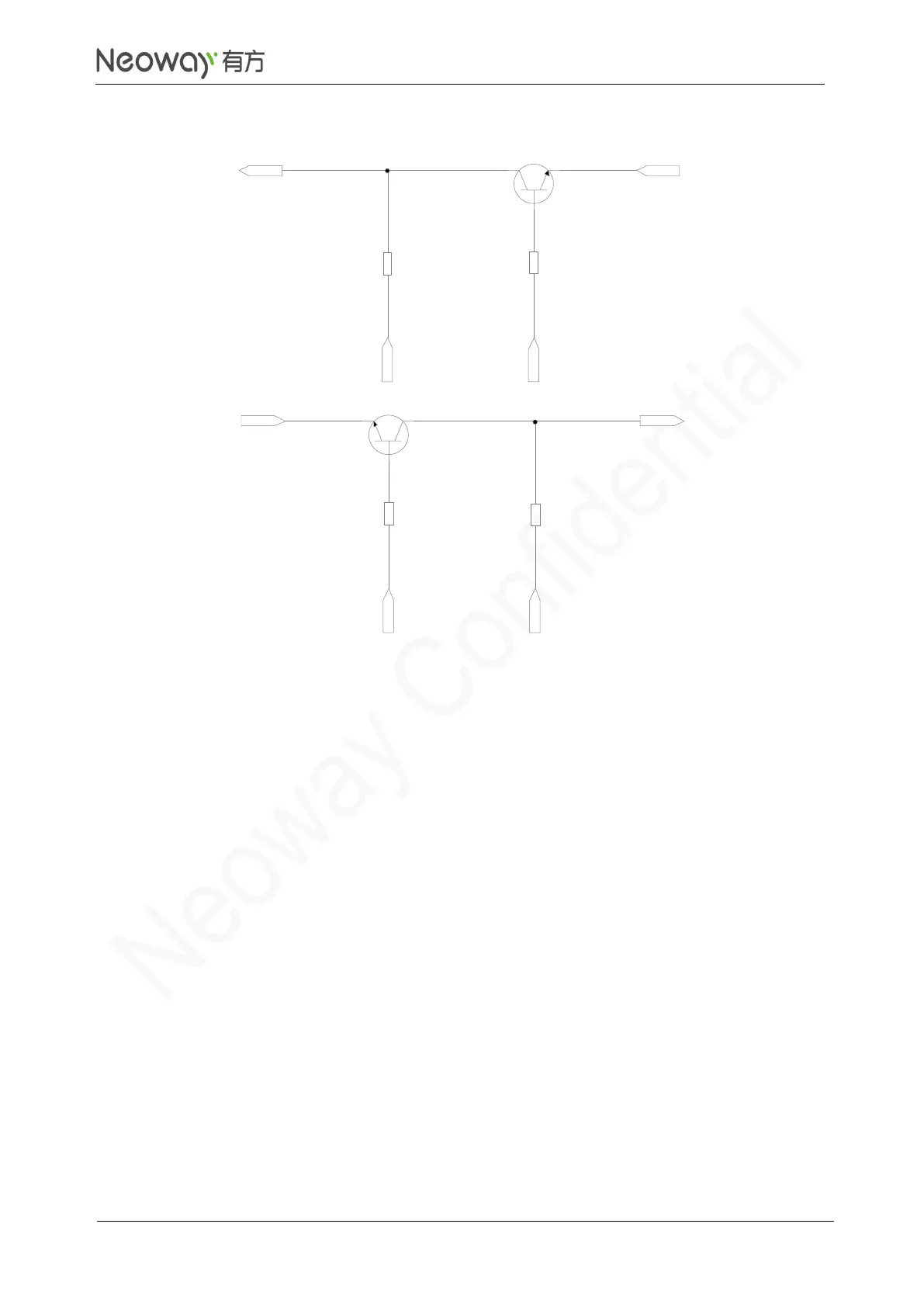
EasyManua.ls Logo

Neoway N11 - Figure 3-11 Level Shifting Circuit 1

Default Icon
52 pages
Print Icon
To Next Page IconTo Next Page
To Previous Page IconTo Previous Page
Loading...
N11
Hardware User Guide
Copyright © Neoway Technology Co., Ltd
17
Figure 3-11 Level shifting circuit 1
UART_TXD
VDDIO_2P8
VCC_IO
4.7 kΩ
10 kΩ
Q1
R2
R3
MCU_RXD
MCU_TXD
VDDIO_2P8
VCC_IO
4.7 kΩ
10 kΩ
Q2
R4
R1
UART_RXD
Components:
R2/R4: 2 kΩ-10 kΩ.
The greater the UART baud rate is, the lower the R2/R4 value is.
R1/R3: 4.7 kΩ-10 kΩ.
The greater the UART baud rate is, the higher the R1/R3 value is.
Q1/Q2: MMBT3904 or MMBT2222
High-speed transistor is better.
If the low level at MCU_UART (V
IL
) is greater than 200mV, use level shifting circuit in Figure 3-12.
Otherwise, low level at UART might be higher than required, resulting in failure to identify signals.

Table of Contents

Related product manuals