EasyManua.ls Logo

NET Corsight CO1041C2 - Page 30

Default Icon
50 pages
Print Icon
To Next Page IconTo Next Page
To Previous Page IconTo Previous Page
Loading...
30/50
Please note that all data and illustrations are subject to error, change and omissionswithout notice. CORSI GH T
Operational Manual - rev. 2.0_10_2016
nected in the SW interface, it gets in high impedance status.
The optocoupler output's logical state is understood as logical 0 when its output transistor is in
high impedance, logical 1 if it is in low impedance m o d e .
The optocoupler output work with operating voltage range of 5-2 4 V .
The maximal switched output current is 100 mA per optocoupler, higher current could damage
the optocoupler output circuit.
The rising edge (switching to logical 1) propagation time is 750 ns, the falling edge propagation
time is under 25 µs. The exact switching speed may vary with temperature and the used input
voltage level the listed specifications are the worst case values.
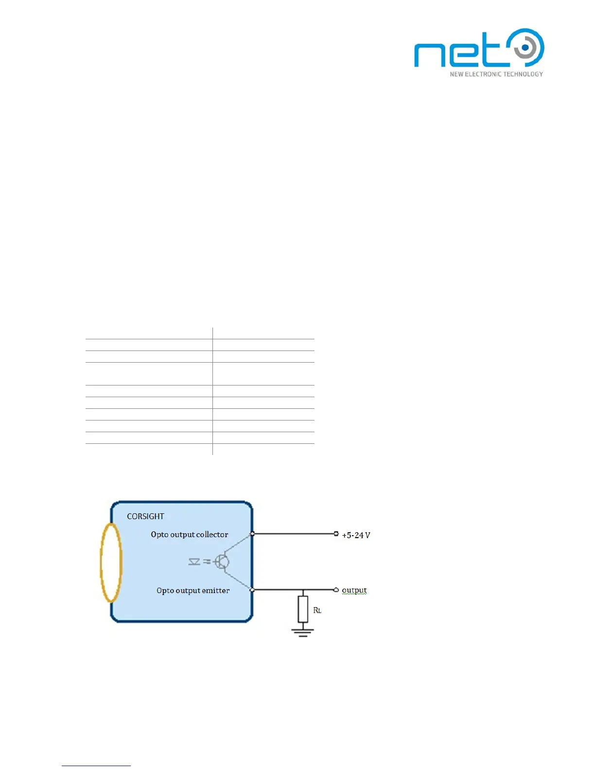
Optocoupler output parameters summary
Parameter
Value
Operating voltage
5—24 V
Output cu rrent
<100 mA
External resistor requirement
Yes, output current must
be limited to 100 mA
OFF to ON delay
750 ns
OFF to ON rise time (10 to 90%)
1.0-4.0 µs
ON to OFF delay
2.4 25 µs
ON to OFF fall time (90 to 10%)
9.0 140 µs
OFF to ON jitter
± 20 ns
ON to OFF jitter
± 0.1 µs
Example of using the optocoupler outputs

Table of Contents