Please note that all data and illustrations are subject to error, change and omissionswithout notice. CORSI GH T
Operational Manual - rev. 2.0_10_2016
An adapter cable is available (see S e c t i o n “Accesso ries
”), with D-sub 25-pin female interface connector.
The table below lists the pinouts also for the connectors of the adapter cable.
I/O connector,
pinout (including pin numbers on the D-sub-25 adapter cable)
Optocoupler Input 3 Anode
Optocoupler Output 1-3 Collector
Optocoupler Output 0 Emitter
Optocoupler Output 1 Emitter
Optocoupler Output 3 Emitter
Optocoupler Input 2 Anode
Optocoupler Input 0 Cathode
Optocoupler Input 0 Anode
Optocoupler Output 0 Collector
Optocoupler Output 2 Emitter
Optocoupler 1 Input Anode
Optocoupler 1-3 Input Cathode
Pins 13, 14, 15, 16, 17, 18, 22, 23 on the D-sub 25 connector are not connected.
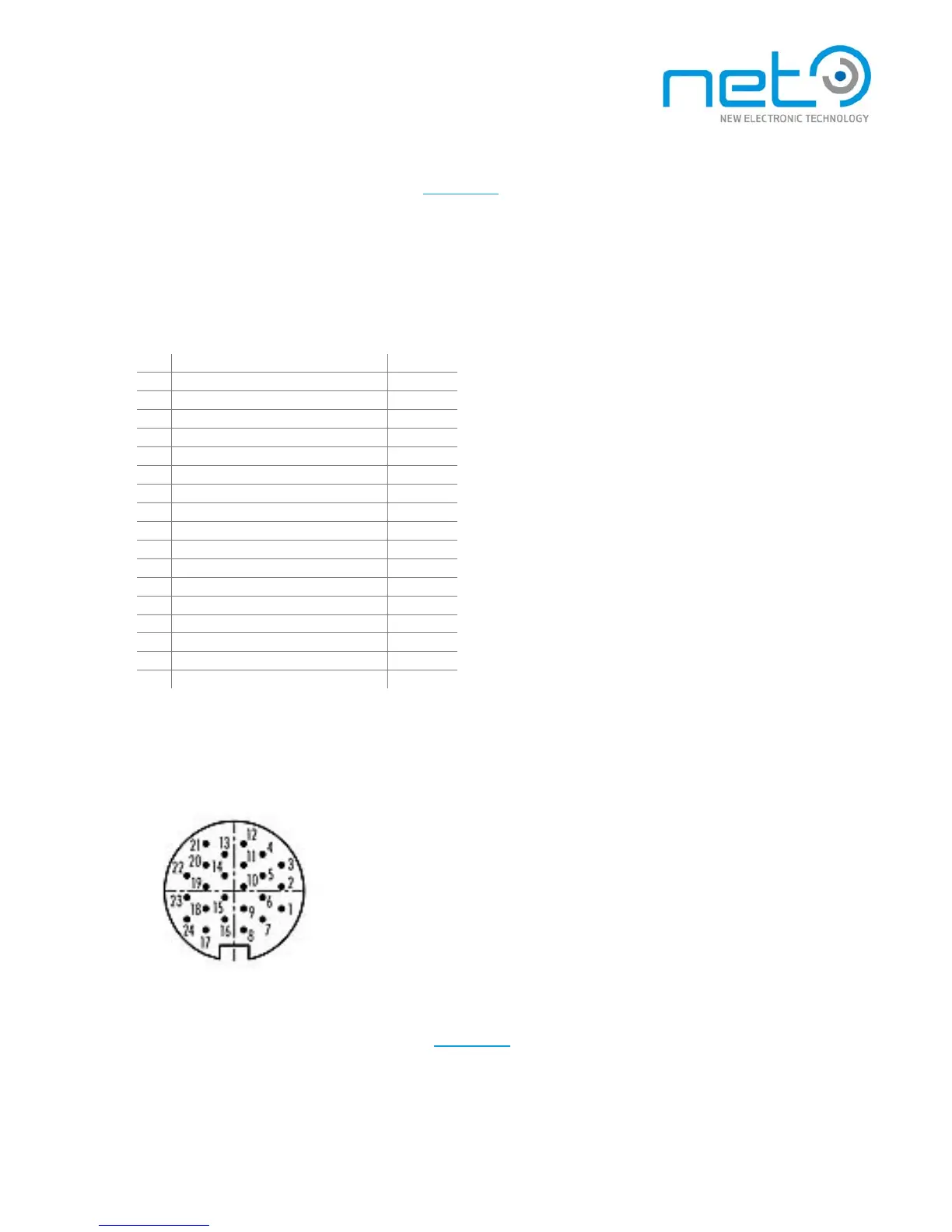
PC system connector
24-pin female M16 connector f o r DP++, RS232 and USB 2.0.
CORSIGHT PC system connector
An adapter cable are available (see Section “Accessories
”), separating individual signal groups into t hre e
dedicated connectors: DP++ male, USB Type A female, and RS232 (D-sub 9-pin male). The table below
lists the pinouts also for the connectors of the adapter cable.