12
SCREENGUARD
™
INSTALLATION AND USER MANUAL
DESCRIPTION
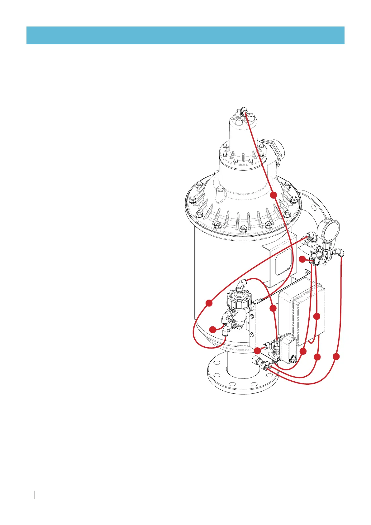
Control tubes
The PE 8 mm command tubes are factory-installed and do not require any intervention during
installation of the filter.
The control-tube connection scheme below is to be used as reference while troubleshooting the filter.
Legend
a.
From the filter inlet pressure point to the
pressure gauge 3-way valve.
b.
From the filter inlet pressure point to the
flush controller PD sensor high-pressure
connection port (right).
c.
From the Aquative solenoid to the pressure
gauge 3-way valve.
d.
From the hydraulic relay to the pressure
gauge 3-way valve.
e.
From the hydraulic relay to the Aquative
solenoid inlet.
f.
From the hydraulic relay to the filter
hydraulic piston cap.
g.
From the pressure gauge 3-way valve to the
flush controller PD sensor low-pressure
connection port (left).
h.
Drain tube (no more than 2 meter long each).
a
h
e
b
c
f
d
g
h
h