EasyManuals Logo

NETGEAR GS748T - ProSafe Smart Switch User Manual

NETGEAR GS748T - ProSafe Smart Switch
36 pages
To Next Page IconTo Next Page
To Previous Page IconTo Previous Page
Page #26 background imageLoading...
Page #26 background image
GS748T Smart Switch Hardware Installation Guide
4-4 Installation
v1.1, September 2007
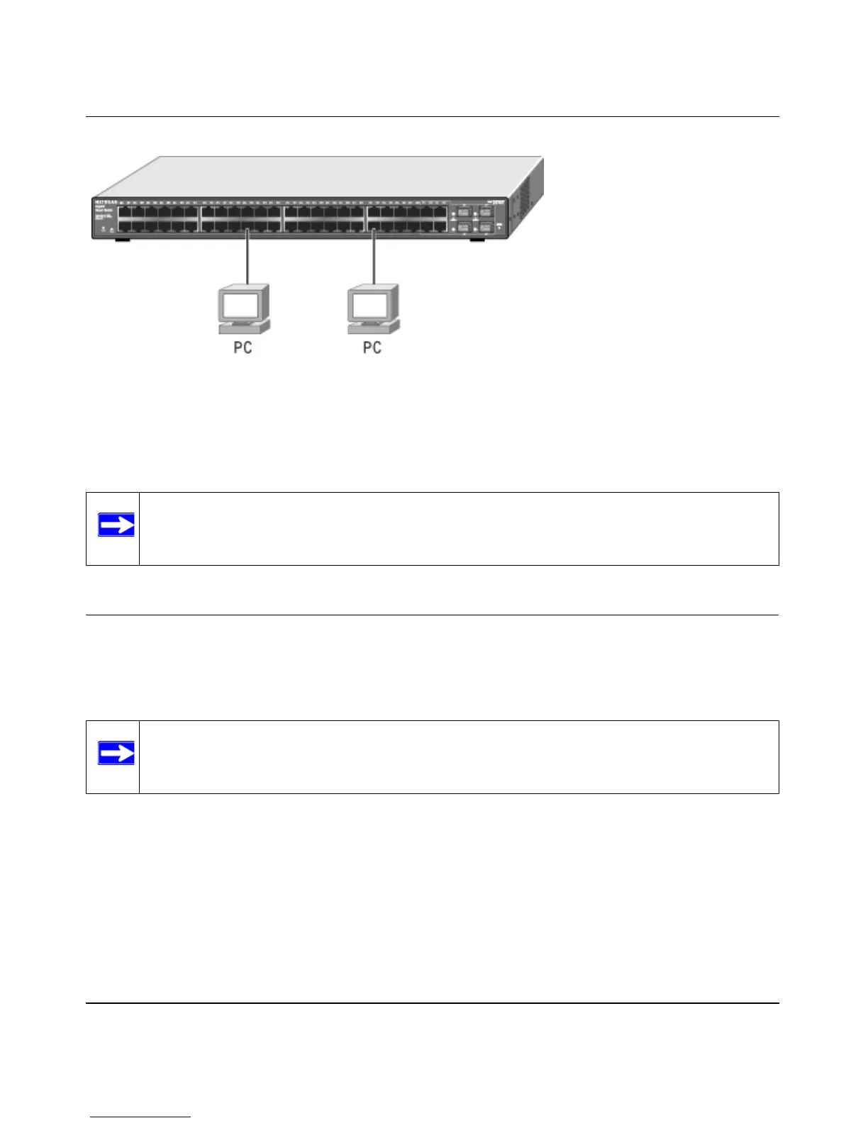
Figure 4-2
Connect each device to an RJ-45 network port on the switch’s front panel (see Figure 4-2) using a
Category 5 (Cat5) unshielded twisted-pair (UTP) cable with RJ-45 connectors.
Step 5: Installing a SFP GBIC Module
The following procedure describes how to install an optional SFP GBIC module into one of the
SFP GBIC module bays of the switch.
To install a SFP GBIC module, insert the SFP module into the SFP GBIC module bay. Press firmly
on the flange of the module to seat it securely into the connector. You can install up to three
additional Gigabit Ethernet modules using this procedure.
Note: Ethernet specifications limit the cable length between the switch and the attached
device to 100 m (328 ft.).
Note: Contact your NETGEAR sales office to buy these modules. If you do not want to
install a SFP GBIC module, skip this procedure.

Questions and Answers:

Question and Answer IconNeed help?

Do you have a question about the NETGEAR GS748T - ProSafe Smart Switch and is the answer not in the manual?

NETGEAR GS748T - ProSafe Smart Switch Specifications

General IconGeneral
ModelGS748T
Device TypeSmart Switch
SFP Slots4
Form FactorRack-mountable
Switching Capacity96 Gbps
MAC Address Table Size8K entries
VLAN SupportYes
QoSYes
Humidity10% to 90% non-condensing
RAM128 MB
Flash Memory32 MB
Power DeviceInternal power supply
Ports48 x 10/100/1000
ManagementWeb-based
Operating Temperature0 - 50 °C
Voltage Required100-240 VAC
Compliant StandardsIEEE 802.3, IEEE 802.3u, IEEE 802.3ab, IEEE 802.3z
FeaturesVLAN support, QoS, port mirroring, SNMP

Related product manuals