Installation
21
NETGEAR GS510TP Smart Switch
Step 3: Checking the Installation
Before applying power to the switch, perform the following:
• Inspect the equipment thoroughly.
• Verify that all cables are installed correctly.
• Check cable routing to make sure cables are not damaged or creating a safety hazard.
• Ensure all equipment is mounted properly and securely.
Step 4: Connecting Devices to the Switch
The following procedure describes how to connect PCs to the switch’s RJ-45 ports. The
GS510TP Smart Switch contains Auto Uplink technology, which allows the attaching of
devices using either straight-through or crossover cables.
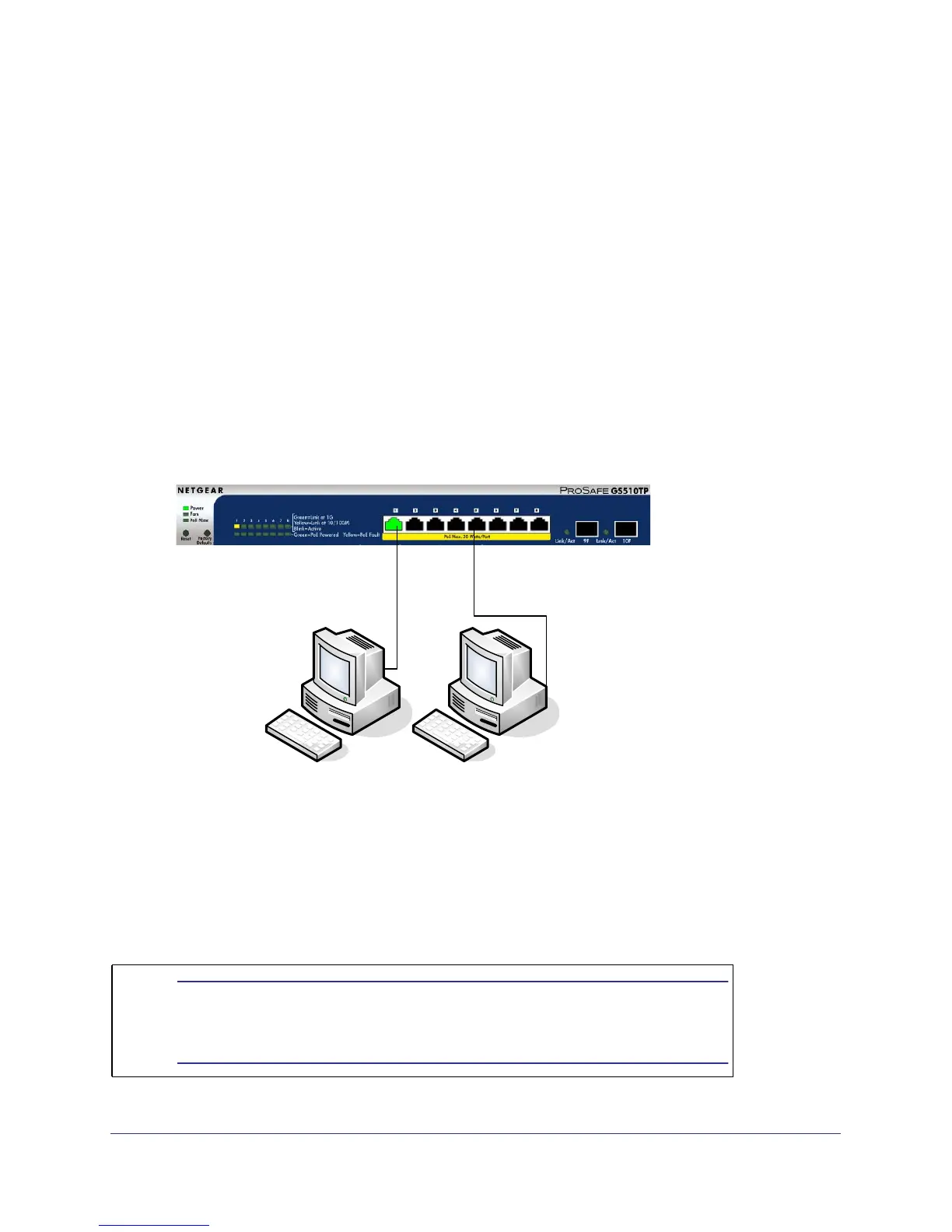
Desktop PC
`
Desktop PC
`
Figure 5. Connect PCs to the Switch’s RJ-45 Ports
Connect each PC to an RJ-45 network port on the Switch front panel (Figure 5). Use
Category 5 (Cat5) Unshielded Twisted-Pair (UTP) cable terminated with an RJ-45 connector
to make these connections.
Note: Ethernet specifications limit the cable length
between the switch and the attached device to 100 m
(328 ft.).
 Loading...