Instruction Manual Model 3100 Analyzer
Manual P/N: C5-06-4900-16-0
Manual file name: MN-A-0005, Rev. C
Page 11
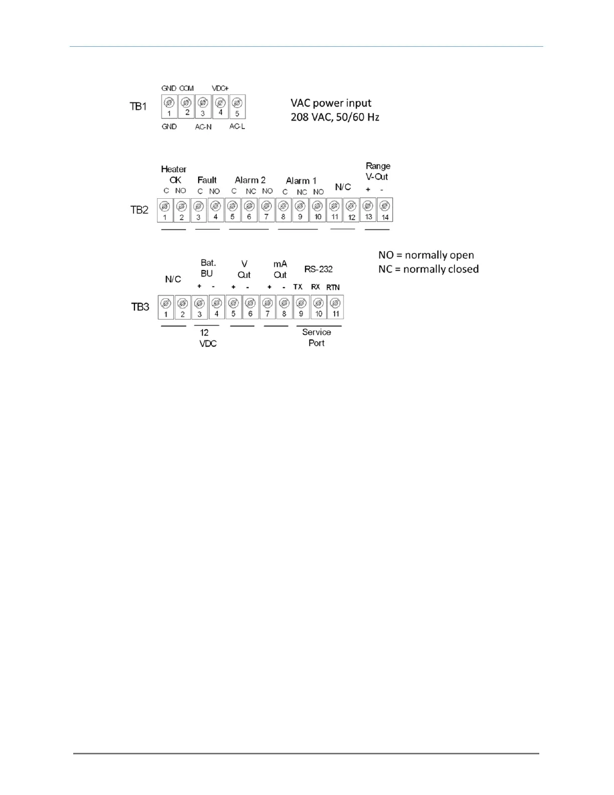
2.1.3.6 Range ID output
Connections from the Range ID output to the user’s auxiliary equipment are made at terminal block TB2
on the rear of the analyzer chassis. Connect the terminal pins in accordance with the schematic shown
on the terminal ID label on the top of the analyzer chassis.
Use 20-AWG, 2-conductor, stranded-wire, twisted pairs for the connections. It is not necessary to use
shielded cable for the Range ID output, with or without electrical barriers. If shielded cable is used, it
should be drained to dc ground at the auxiliary equipment.
2.1.3.7 Analog voltage output
Connections from the analog voltage output to the user’s auxiliary equipment are made at terminal block
TB3 on the rear of the analyzer chassis (see Figure 10). Connect the terminal pins in accordance with
the schematic shown on the terminal ID label on the top of the analyzer chassis.
Use 20-AWG, 2-conductor, stranded-wire, twisted pairs for the connections. It is not necessary to use
shielded cable for the Analog voltage output, with or without electrical barriers. If shielded cable is used,
it should be drained to dc ground at the auxiliary equipment.
2.1.3.8 Analog current output
Connections from the analog current output to the user’s auxiliary equipment are made at terminal block
TB3 on the rear of the analyzer chassis. The analog current output is a negative ground, non-isolated 0-
20mA, or 4-20 mA current loop. 12 VDC power is supplied internally by the Model 3100 analyzer.
Maximum electrical loading is 250 Ohms. Connect the terminal pins in accordance with the schematic
shown on the terminal ID label on the top of the analyzer chassis.
Fig. 10, Analyzer electrical connections