Model 3100 Analyzer Instruction Manual
Page 12
Manual file name: MN-A-0005, Rev. C
Manual P/N: C5-06-4900-16-0
Use 20-AWG, 2-conductor, stranded-wire, twisted pairs for the connections. It is not necessary to use
shielded cable for the Analog current output, with or without electrical barriers. If shielded cable is used, it
should be drained to dc ground at the auxiliary equipment.
2.1.3.9 Battery backup
12-volt DC battery backup terminals are provided at terminal block TB3 on the rear of the analyzer
chassis. These terminals may be connected to a fixed 12 VDC power source to act as a backup in case
mains power has been lost. The circuit will detect loss of the mains power and the VDC battery backup
will maintain power to the system.
Connection to the battery backup is not required for normal operation of the analyzer. Connect the
terminal pins in accordance with the schematic shown on the terminal ID label on the top of the analyzer
chassis.
2.1.3.10 RS-232 service port
Connections from the Range ID output to the user’s auxiliary equipment are made at terminal block TB3
on the rear of the analyzer chassis. Connect the terminal pins in accordance with the schematic shown
on the terminal ID label on the top of the analyzer chassis.
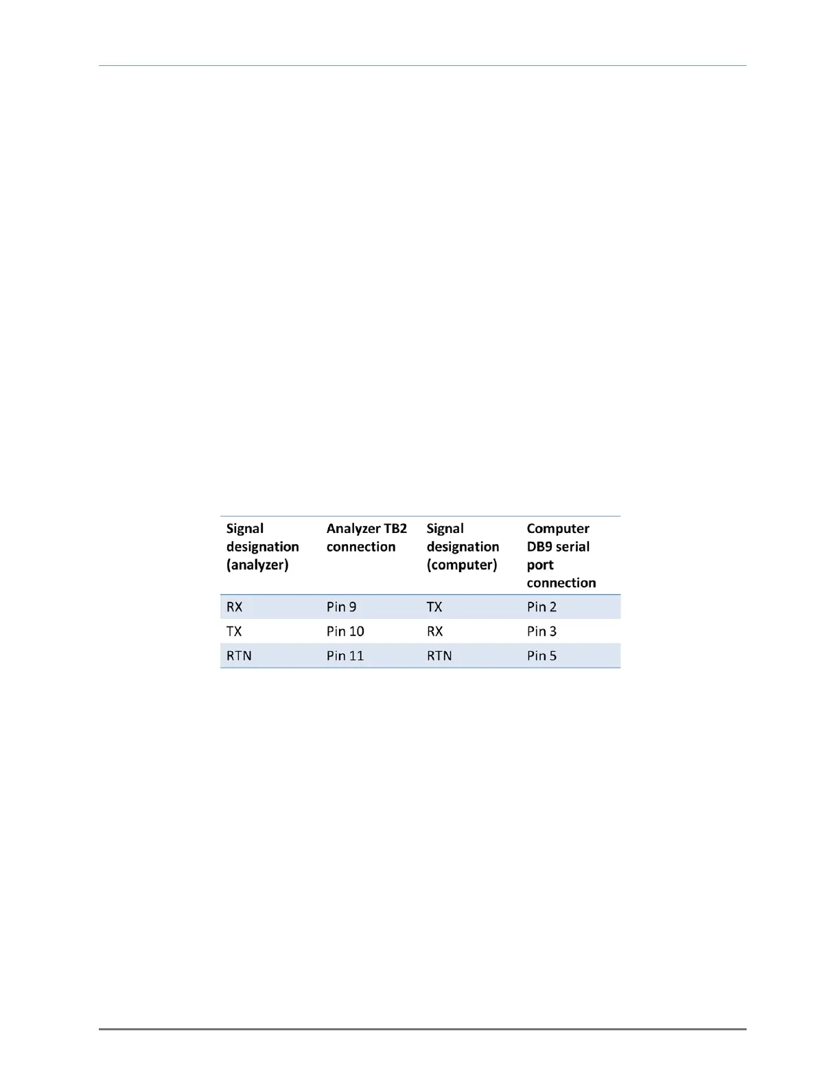
For interfacing with any standard PC computer via the serial port, use 20-AWG 3-conductor shielded,
stranded-wire, jacketed cable -- terminated on one end with a female DB9 connector (see Figure 11).
The shielding should be drained to dc ground at the computer.
2.1.3.11 Mains power
Connections for Mains Power input are made at terminal block TB1 on the rear of the analyzer chassis.
Connect the terminal pins in accordance with the schematic shown on the terminal ID label on the top of
the analyzer chassis.
For VAC versions, use minimum 16-AWG 3-conductor, stranded-wire, for the connections. Supply single-
phase 110/208 ±10% VAC, 50/60 Hz to the unit. For VDC versions, use 18-AWG, 3-conductor, stranded-
wire, for the connections. Supply 12/24 VDC to the unit.
Fig. 11, Analyzer electrical connections