Instruction Manual Model 3100 Analyzer
Manual P/N: C5-06-4900-16-0
Manual file name: MN-A-0005, Rev. C
Page 21
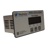
4.1.1.1 User Setup Mode A: Display range select
Setup Mode A allows the user to map the display and electrical output range scale of the Model 3100 to
suit the application (see Appendix E – Range / Output Chart). Valid settings are listed in Figure 15.
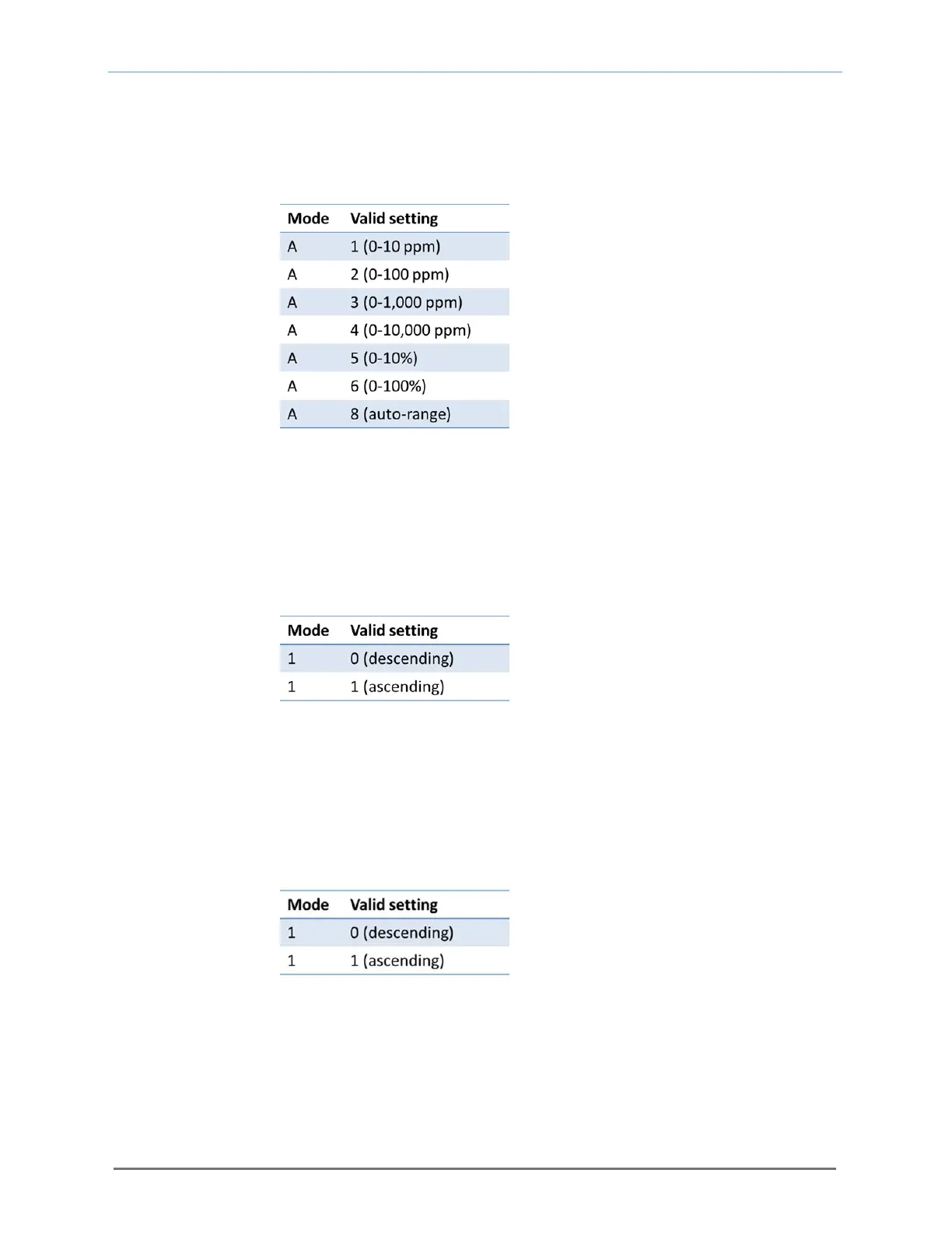
4.1.1.2 User Setup Mode 1: Alarm-1 relays (descending or ascending)
Setup Mode 1 allows the user to set the Alarm-1 relay action to descending (the relay is set to its active
state when the oxygen level is below the Alarm-1 level set point) or ascending (the relay is set to its active
state when the oxygen level is above the Alarm-1 level set point). Valid settings are listed in Figure 16.
4.1.1.3 User Setup Mode 2: Alarm-2 relays (descending or ascending)
Setup Mode 2 allows the user to set the Alarm-2 relay action to descending (the relay is set to its active
state when the oxygen level is below the Alarm-1 level set point) or ascending (the relay is set to its active
state when the oxygen level is above the Alarm-1 level set point). Valid settings are listed in Figure 17.
4.1.1.4 User Setup Mode 3: Analog voltage output setting
Setup Mode 3 allows the user to set the Analog Output Voltage full scale to 1, 5, or 10 volts. Note that
the software settings must match the RA and RB jumper settings on the Main CPU PCB (section 4.1.3).
Valid settings are listed in Figure 18.
Fig. 15, Valid settings for setup Mode A
Fig. 16, Valid settings for setup Mode 1
Fig. 17, Valid settings for setup Mode 2