Manual Part Number:
5-06-7000-65-0
Manual File:
MN-A-0117 Rev. D
Revision Date: August 24, 2006 Page 1-13
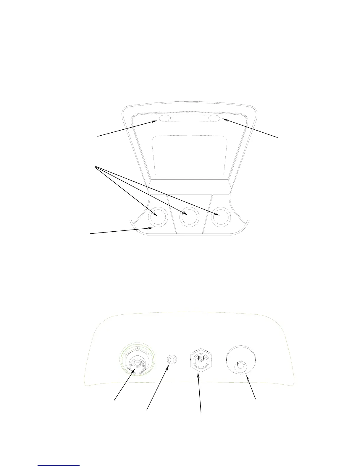
1.3.6 Control Panel
The Control Panel serves as the main user interface. The Control Panel features three soft key
buttons that change their function as the instrument changes modes. The current function for
each button is displayed by the soft key label at the bottom of the graphic display. Red and Green
LED’s at the top of the Control Panel are used for visual Pass/Fail indications.
1.3.7 Back Panel Connections
The connections located on the back panel are illustrated below.
CAUTION: The sample outlet port should never be obstructed. Keep the sample outlet port
free and clear at all times.
Green LED
Red LED
Soft Key
Buttons
Sample Inlet
Sample Outlet
Battery Charge Port
12VDC Power Input
(Battery Clips)
Power
On/Off
Graphic
Display