Do you have a question about the Neutronics 7100E and is the answer not in the manual?
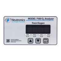
Overview of the Neutronics Model 7100E analyzer.
Key features of the Model 7100E Compact Series analyzer.
Details the main internal components of the analyzer.
Describes the main board's function and components.
Explains the relay board's role in alarm and control.
Details the power supply board and its input options.
Describes the display board's function for output and codes.
Details the user interface keypad and status LEDs.
Details the mini-zirconia sensor technology and operation.
Describes the sensor mounting base for sample monitoring.
Details the stainless steel enclosure for protection.
Details the various inputs and outputs of the analyzer.
Details the electrical input for the oxygen sensor.
Explains the Alarm-1 relay and its configuration.
Explains the Alarm-2 relay and its configuration.
Describes the fault relay and its output function.
Details the analog voltage output for data indication.
Details the analog current output for data indication.
Explains the output for identifying the measurement range.
Details the RS-232 service port for communication.
Explains the physical interface of the control panel.
Describes the function of the UP button.
Describes the function of the DOWN button.
Describes the function of the MODE button.
Explains the main display for readings and status.
Describes the RUN, Alarm, and Fault indicator LEDs.
Specifies the intended applications for the analyzer.
Critical safety precautions for operating the analyzer.
Outlines the steps for installing the analyzer unit.
Details locating and mounting the analyzer.
Details installing the remote sensor assembly.
Describes mounting the flow-through sensor head.
Details pneumatic connections for sample inlet and exhaust.
Details the final steps for analyzer installation.
Connects the sensor to the flow-through head.
Groups terminal block connections for power, alarms, and I/O.
Explains connections for Alarm-1 and Alarm-2 relay outputs.
Explains connection for the fault relay output.
Explains connection for the Range ID output.
Details connections for analog voltage and current outputs.
Details connections for battery backup and RS-232.
Details connections for mains power input.
Guides through initial power up and calibration.
Describes the initial power-up sequence and self-test.
Details recommended calibration procedures.
Guides on setting alarm thresholds.
Overview of analyzer's operational modes and user modes.
Details how to initiate and use various user modes.
Explains calibration process for accurate readings.
Guides on setting or viewing Alarm-1 parameters.
Guides on setting or viewing Alarm-2 parameters.
Allows viewing of active system faults.
Process for returning the analyzer to normal operation.
Describes the analyzer's operating states.
Describes the initial self-test and warm-up routine.
Explains the normal operating mode of the analyzer.
Describes the condition when Alarm-1 is active.
Describes the condition when Alarm-2 is active.
Describes the condition when a fault is active.
Guides on configuring the analyzer settings.
Explains how to configure settings using the control panel.
Allows mapping display and output ranges.
Sets Alarm-1 relay action (asc/desc).
Sets Alarm-2 relay action (asc/desc).
Sets the analog voltage output scale.
Sets the RS-232 communication output format.
Sets the low-end calibration gas range.
Sets alarm relay fail-safe behavior.
Sets the RS-232 communication baud rate.
Restores analyzer to factory default settings.
Explains configuration via PC connection.
Details connecting and using HyperTerminal for setup.
Guides on resolving connection issues.
Explains data access levels via RS-232.
Details accessing data and parameters at standard level.
Disables automatic data dumping.
Sets output to human-readable format.
Sets output to machine format without checksum.
Sets output to machine format with checksum.
Sets output to tab-delimited format.
Accesses user setup mode via PC.
Accesses advanced settings with password.
Navigates the RS-232 setup menu.
Restores factory settings via RS-232.
Lists current analyzer settings.
Configures alarm and relay settings.
Sets fail-safe behavior for alarm relays.
Sets the threshold for Alarm-1.
Configures Alarm-1 action as ascending or descending.
Sets the threshold for Alarm-2.
Configures Alarm-2 action as ascending or descending.
Sets minimum time relays hold active state.
Sets fault relay status during warm-up.
Sets time relays remain in last state after menu exit.
Configures analog voltage and current outputs.
Sets the analog voltage output full-scale value.
Sets the analog current output range.
Enables manual override of analog output mapping.
Sets zero point for analog voltage output.
Sets max point for analog voltage output.
Sets minimum point for analog current output.
Sets maximum point for analog current output.
Maps display and analog output range scales.
Configures RS-232 serial communication options.
Sets the RS-232 baud rate.
Sets the format of timed RS-232 output.
Sets the rate of RS-232 data packet transmission.
Note on unused OA1 style output.
Prevents changing alarm setpoints.
Prevents changing gas calibration values.
Prevents manual initiation of user modes from panel.
Sets acceptable LOW calibration gas range.
Sets time before auto return to RUN mode.
Note regarding unused setting.
Explains changing settings via hardware jumpers.
Configuring analog output via hardware jumpers.
Provides a schedule for maintenance tasks.
Guides on diagnosing and resolving issues.
Lists and explains fault codes and their causes.
Indicates sensor heating during startup.
Indicates relays are inactive during stabilization.
Indicates device is in setup mode via service port.
Indicates analog output exceeds configured range.
Indicates analog output is below configured range.
Indicates concentration reading is not ready.
Indicates a broken electrical connection to the sensor.
Indicates reading outside configured range.
Indicates calibration reading is too high.
Indicates calibration reading is too low.
Indicates faulty sensor or procedure during calibration.
Lists available spare parts for the analyzer.
Provides detailed technical specifications of the analyzer.
Lists default factory configuration settings.
Details quick functions accessible via control panel keys.
Details range and corresponding analog output values.
Lists available settings for zero calibration range.
Describes the intended operator and application for the analyzer.
| Brand | Neutronics |
|---|---|
| Model | 7100E |
| Category | Measuring Instruments |
| Language | English |