Step 1 – locate and mount the analyzer unit
The Model 7100E is designed to be mounted flush to the surface of a stationary equipment control panel.
Select a suitable location for the analyzer unit where the digital display and status LEDs will be easy to
read, and the interface buttons on the display panel will be easy to access.
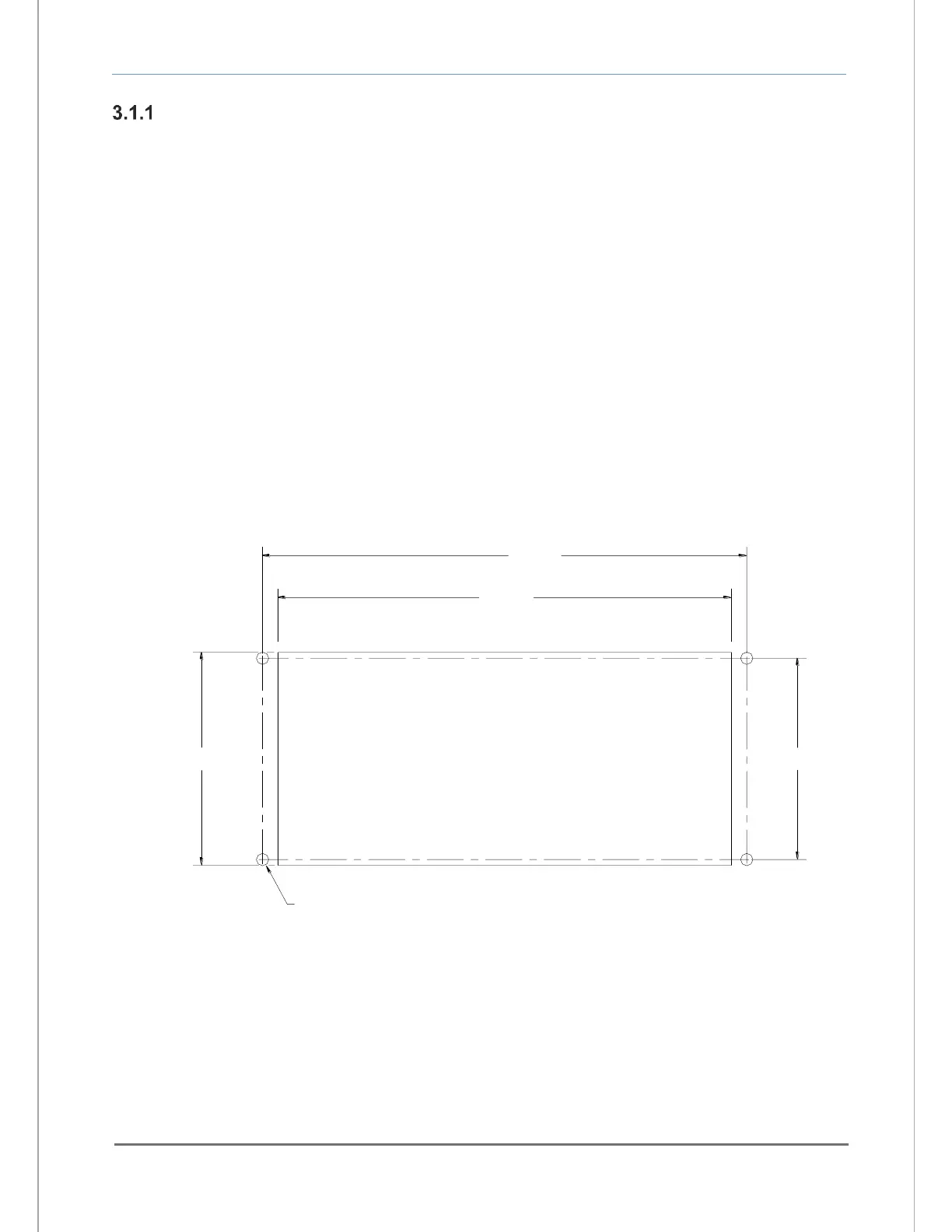
Cut and drill the mounting panel in accordance with the specifications shown in Figure 8. Clearance
holes for the #8-32 threaded mounting studs do not need to be tapped. Hex nuts are included to secure
the unit to a panel. Trim all burrs or sharp edges in the cutout or mounting-holes, which would interfere
with or damage the gasket on the analyzer control panel.
Slide the analyzer unit into the cutout, rear-chassis first, and seat the control panel gasket on the
mounting surface. The gasket on the analyzer control panel ensures a watertight seal around the control
panel cutout. Secure the threaded mounting studs with the supplied hex-nuts, and internal-tooth lock-
washers. The analyzer front control panel is suitable for NEMA Type 4, IP66 environments when properly
installed. The rear electronics chassis is suitable for NEMA Type 1, IP 20 environments.
The analyzer should not be exposed to water, adverse temperature, or shock. Ensure the analyzer unit is
mounted in an area of free airflow to prevent the chassis from exceeding the operating temperature
specifications. Do not mount the analyzer or sensor against hot surfaces. Do not block the ventilation
louver on the analyzer chassis.