4.2.1.5 CALIBRATION Step-4: Calibrate the Model 7100E LOW
After a regulated stream of LOW calibration gas has been applied to the sensor press and release the
“MODE” key once. The 7-segment alphanumeric display will show “CAL”, then an oxygen concentration
value. Adjust the displayed oxygen concentration value to read the applied calibration gas oxygen
concentration by pressing the “UP” or “DOWN” arrow key as required. Press and release the “MODE”
key four times to return to Run mode.
4.2.1.6 CALIBRATION Step-5: Apply HIGH calibration gas to the oxygen sensor
Attach a pre-selected HIGH calibration gas (section 3.2.1.2.2) to the Model 5100E sensor flow through
head. The user may attach the regulated gas source to the sensor head sample inlet port directly, or
through a fixed gas manifold. The latter method will help to prevent premature wear of tube-ends and
fittings, and increase long-term sampling system integrity. Where a calibration manifold has not been
installed, connect the calibration gas source to the oxygen sensor similar to section 2.1.2.2.
Apply calibration gas to the oxygen sensor. Adjust the regulated calibration gas pressure to match the
pressure of the in-service sample gas, within the sensor pressure specification of 1-10 PSIG (Appendix
B). Be sure to flow calibration gas to the sensor until the analyzer display has stabilized to allow
calibration gas to sweep out the sample lines.
4.2.1.7 CALIBRATION Step-6: Calibrate the Model 7100E HIGH
After a regulated stream of HIGH calibration gas has been applied to the sensor press and release the
“MODE” key once. The 7-segment alphanumeric display will show “CAL”, then an oxygen concentration
value. Adjust the displayed oxygen concentration value to read the applied calibration gas oxygen
concentration by pressing the “UP” or “DOWN” arrow key as required. Press and release the “MODE”
key four times to return to Run mode.
4.2.1.8 CALIBRATION Step-7; Return the oxygen sensor to online service
When calibration procedures are complete, the Model 7100E is ready to return to service. Disconnect
calibration gas from the oxygen sensor by completely removing the installed 1/8" FNPT fitting from the
sensor flow-through head sample inlet port. If a calibration manifold has not been installed, reconnect the
sample inlet port to the process for in-service oxygen measurement (section 2.1.2.2). If an alternate vent
connection has been made, reconnect the sensor flow-through head sample exhaust port to the primary
vent source (section 2.1.2.3). Be sure to flow sample gas to the sensor until the analyzer display has
stabilized to allow time to sweep the sample lines clear of calibration gas.
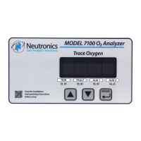
SET/VIEW ALARM-1 Mode
To enter Set Alarm-1 mode from run mode using the keypad; scroll through the user mode menu by
pressing momentarily the “MODE” key two (2) times, until the 7-segment alphanumeric display reads
“AL1” (set Alarm-1 level), and the “RUN” and “ALM1” indicator LED’s flash. The display will show
momentarily “AL1” and then the current Alarm-1 threshold level (an O
2
concentration). Use the “UP” and
“DOWN” keys to adjust the Alarm-1 setpoint level. Changed settings are automatically saved when the
“MODE” key is pressed to enter the next mode.