1 Contents
Welcome ....................................................................................................................................................... 5
Notice ............................................................................................................................................................ 5
Safety instructions ......................................................................................................................................... 6
Designated use ............................................................................................................................................. 6
Operational safety ......................................................................................................................................... 6
2 Introduction and overview ..................................................................................................................... 7
2.1 General .......................................................................................................................................... 7
2.2 Features ........................................................................................................................................ 7
2.3 System hardware overview ........................................................................................................... 9
Main board ............................................................................................................................ 9
Relay board ........................................................................................................................... 9
Power supply ......................................................................................................................... 9
Display board ........................................................................................................................ 9
Control panel ......................................................................................................................... 9
Sensor ................................................................................................................................. 10
Sensor flow-through head ................................................................................................... 10
Enclosure (chassis) ............................................................................................................. 11
2.4 Analyzer inputs and outputs ........................................................................................................ 13
Oxygen sensor input ........................................................................................................... 13
Alarm-1 relay output ............................................................................................................ 13
Alarm-2 relay output ............................................................................................................ 13
Fault relay output................................................................................................................. 13
Analog voltage output ......................................................................................................... 13
Analog current output .......................................................................................................... 14
Range ID output .................................................................................................................. 14
Service port ......................................................................................................................... 14
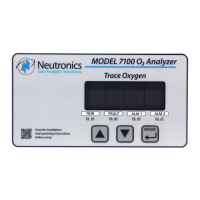
2.5 Control panel user interface ........................................................................................................ 14
The “UP” pushbutton ........................................................................................................... 14
The “DOWN” pushbutton .................................................................................................... 14
The “MODE” pushbutton ..................................................................................................... 14
7-segment alphanumeric display ........................................................................................ 15
RUN indicator LED .............................................................................................................. 15
Alarm-1 indicator LED ......................................................................................................... 15
Alarm-2 indicator LED ......................................................................................................... 15
Fault indicator LED .............................................................................................................. 15