Reminder: When selecting gases for two-point calibration, remember that one must be within the
Low End Calibration range setting, and the other outside of that range. If none, or both selected
calibration gases are within the Low End Calibration range, the Model 7100 analyzer will not
operate properly.
WARNING: Calibrating the Model 7100 on < 10 PPM oxygen concentration will cause the unit to
operate improperly. Do not calibrate the Model 7100 on zero-gas.
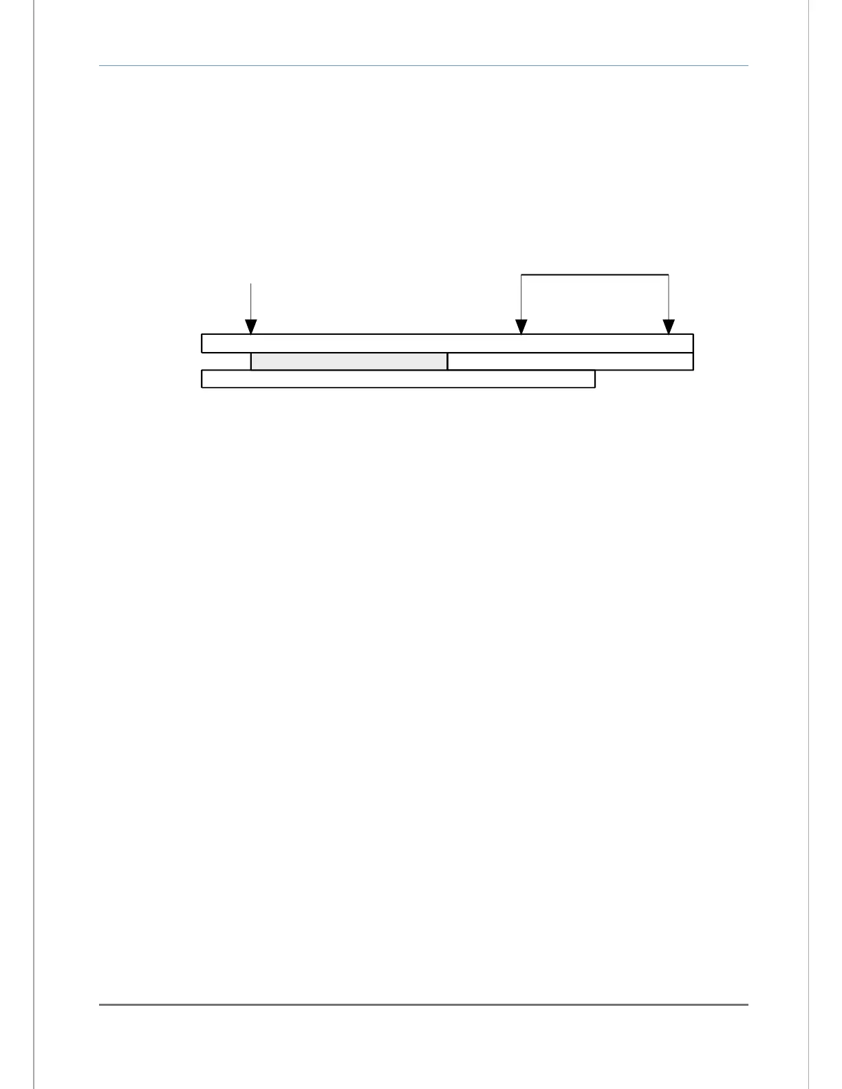
Configured Analyzer range (0-100 PPM)
Measurement range (0-80 PPM)
Low calibration range (10-50 PPM)
Low calibration gas - acceptable range 10-50 PPM
(within factory default low-end calibration range setting ).
Use 10 PPM calibration gas
High calibration gas - acceptable range 51-100 PPM
(above low-end calibration range setting ).
High calibration range (51-100 PPM)
Use ~65 to ~95 PPM
Calibration gas
4.2.1.3 CALIBRATION Step-2: Remove the oxygen sensor from online service
The oxygen sensor requires removal from on-line service to perform calibration. Calibration or other
maintenance of the Model 7100E analyzer and sensor should be performed when the measured process
is not operating. If the unit has been installed with a Neutronics process sampling system, please refer to
the equipment manual for detailed instructions.
Warning Before opening any part of the sampling system to air, make sure that the sampling lines are not
pressurized, and are clear of any gas that may create a personnel or environmental hazard.
Disconnect the measured process from the sensor by completely removing the installed 1/8" MNPT
fittings from the sensor flow-through head sample inlet port (this step is not necessary if using a fixed gas
manifold – section 2.3.1). If it is necessary to exhaust to an alternate path during calibration, completely
remove the installed 1/8” MNPT fittings from the sensor flow-through head sample exhaust port. Connect
the oxygen sensor to an alternate exhaust location as in section 2.1.2.3.
4.2.1.4 CALIBRATION Step-3: Apply LOW calibration gas to the oxygen sensor
Attach a pre-selected LOW calibration gas (section 3.2.1.2.1) to the sensor flow through head. The user
may attach the regulated gas source to the sensor head sample inlet port directly, or through a fixed gas
manifold. The latter method will help to prevent premature wear of tube-ends and fittings, and increase
long-term sampling system integrity. Where a calibration manifold has not been installed, connect the
calibration gas source to the oxygen sensor similar to section 2.1.2.2.
Apply calibration gas to the oxygen sensor. Adjust the regulated calibration gas pressure to match the
pressure of the in-service sample gas, within the sensor pressure specification of 1-10 PSIG (Appendix
B). Be sure to flow calibration gas to the sensor until the analyzer display has stabilized to allow
calibration gas to sweep out the sample lines.
Warning: Never apply an unregulated gas supply to the oxygen sensor. High or uncontrolled pressures
may damage the oxygen sensor, and/or sampling system components.