3.1.3.1 Alarm-1 relay output
Connections from the Alarm-1 relay contacts to the user’s process control equipment are made at
terminal block TB2 on the rear of the analyzer chassis. The oxygen alarm relay contacts are voltage-free
Form C relay contacts, SPDT, 5A @ 250 VAC, 5A @ 30 VDC. Be certain to match the terminal pins
against the terminal ID label on the top of the analyzer chassis.
3.1.3.2 Alarm-2 relay output
Connections from the Alarm-2 relay contacts to the user’s process control equipment are made at
terminal block TB2 on the rear of the analyzer chassis. The oxygen alarm relay contacts are voltage-free
Form C relay contacts, SPDT, 5A @ 250 VAC, 5A @ 30 VDC. Be certain to match the terminal pins
against the terminal ID label on the top of the analyzer chassis.
3.1.3.3 Fault relay output
Connections from the fault relay contacts to the user’s process control equipment are made at terminal
block TB2 on the rear of the analyzer chassis. The fault relay contacts are voltage-free Form B relay
contacts, SPST, 5A @ 250 VAC, 5A @ 30 VDC. Be certain to match the terminal pins against the
terminal ID label on the top of the analyzer chassis.
3.1.3.4 Range ID output
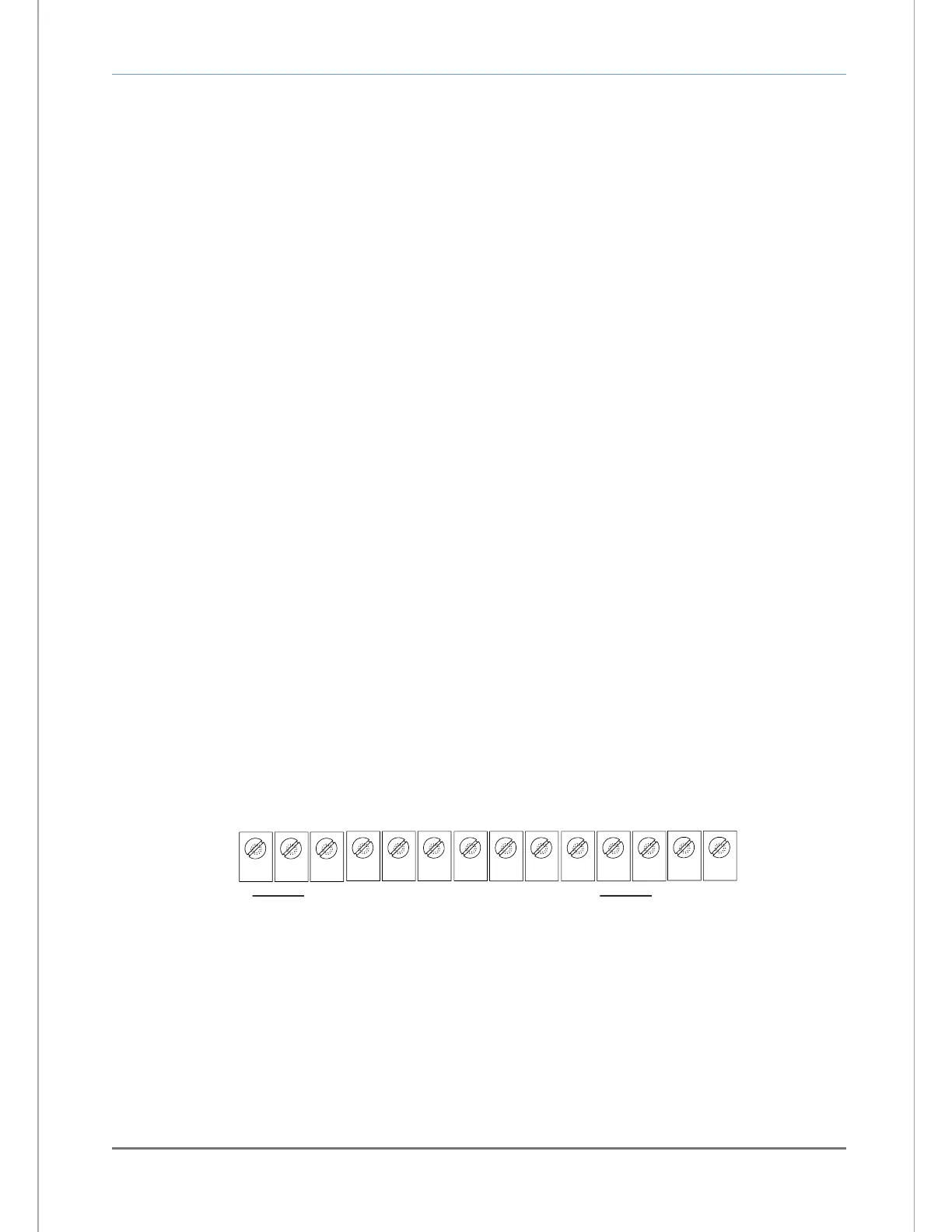
Connections from the range ID output to the user’s auxiliary equipment are made at terminal block TB2
on the rear of the analyzer chassis (Figure 13). Be certain to match the terminal pins against the terminal
ID label on the top of the analyzer chassis.
Use 20-AWG, 2-conductor, stranded-wire, twisted pairs for the connections. It is not necessary to use
shielded cable for the Range ID output, with or without electrical barriers. If shielded cable is used, it
should be drained to dc ground at the auxiliary equipment.