Model 7100E System installation and start-up
Manual P/N: C5-06-4900-14-0
Revision A, dated 24-Jun-2016
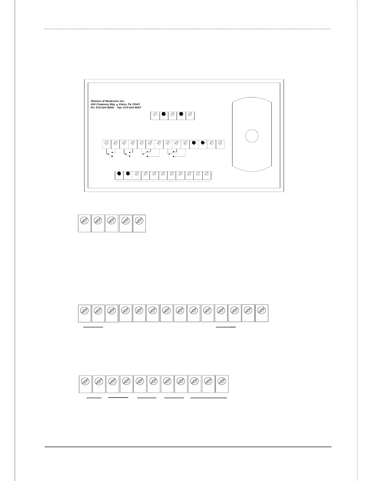
A label depicting the terminal block arrangement is affixed to the top of the chassis for easy reference
during installation and maintenance (VAC configuration shown in Figure 12). The terminal blocks feature
screwed terminals. The terminal blocks are also removable for ease of wiring or removal of the analyzer
module.
V-OUT
RANGE
TB1
TB2
NO
7
V-OUT
115/230 VAC, 50/60 Hz, 5 W atts, m ax.
TB3
* *
1 2
12V DC
4
BAT. BU
3
+ -
5
+
NO
FAULT
CC NO
21 3
TEM P
NCC
4 5 6
ALARM 2
1
SERVICE PORT
TX
AN ALOG
I-OUT
6 7
- +
8
-
RS-232
9 10
RX
11
RTN
NOC NC
8 109
ALARM 1
2 3 4
*
+
*
1211 13
5
TRON
PROCESS ANALYZER DIVISION
N
GND LINENEU
POW ER INPUT
* *
NO CONNECTION
*
-
14
SENSOR CABLE
1 2 3
no
connection
TB2
4 5 6 7 8 9 10 11
12
13
14
Fault
C NO
Alarm 1
C
NC
NO
Alarm 2
C
NC
NO
Range
V-Out
+ -
1 2 3
TB3
4 5 6 7 8 9 10 11
Bat.
BU
+ -
V
Out
+ -
mA
Out
+ -
RS-232
TX RX
RTN
12
VDC
no
connection
no
connection
Service
Port
NO = Normally Open
NC = Normally Closed
C = Common
VAC POWER INPUT,
90-264 VAC, 47-63 Hz
VDC POWER INPUT,
11-18 VDC / 20-30 VDC
1 3
TB1
GND
5
VDC+
2 4
COM
GND
AC-N
AC-L
- or -
* Refer to Appendix C - Factory Configuration for the
correct DC voltage to use with your unit
Fig. 12, analyzer chassis electrical connections