3.1.2.2 Sample inlet port
Pneumatic connection to the measured process for sample extraction is made at either of the two
interchangeable 1/8” FNPT fittings around the side of the flow-through head. For connecting the flow-
through head to the measured process, use 1/8" or 1/4" rigid tubing, and 1/8" MNPT fittings of a material
compatible with process gas composition. Ensure that no grease, particulate, or solvent is present in the
tubing during installation. Use thread-tape to seal connections, and prevent galling. Fix all sample tubing
and connectors.
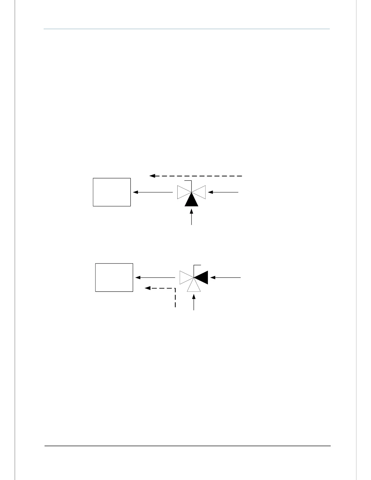
A fixed calibration port (Figure 11) may be implemented in the process sampling line by installing a 1/8" or
1/4" 3-way manual ball valve into the sampling line as in figure-9. Use 1/8" or 1/4" rigid tubing and 1/8"
MNPT fittings of a material compatible with process gas composition. Ensure that no grease, particulate,
or solvent is present in the tubing during installation. Use thread-tape to seal connections, and prevent
galling. Fix all sample tubing and connectors.
3.1.2.3 Sample exhaust port
Pneumatic connection to the measured process for sample extraction is made at either of the two
interchangeable 1/8" FNPT fitting around the side of the flow-through head, but opposite the installed
sample inlet port (section 2.1.2.2). For connecting the sample exhaust to vent, use 1/8" or 1/4" rigid
tubing and 1/8" MNPT fittings of a material compatible with process gas composition. Select a vent
location that is known to be at atmospheric pressure at all times. Use a minimum of 2-meters of tubing to
prevent back-flow of vent gas to the sensor. Ensure that no grease, particulate, or solvent is present in
the tubing during installation. Use thread-tape to seal connections, and prevent galling. Fix all sample
tubing and connectors.