System installation and start-up Model 7100E
Revision A, dated 24-Jun-2016
Manual P/N: C5-06-4900-14-0
3.1.3.8 RS-232 Service port
Connections from the range ID output to the user’s auxiliary equipment are made at terminal block TB3
on the rear of the analyzer chassis. Be certain to match the terminal pins against the terminal ID label on
the top of the analyzer chassis.
For interfacing with a standard PC computer via serial port, use 20-AWG, 3-conductor, shielded, stranded
wire, jacketed cable, terminated on one end with a female DB9 connector. The shielding should be
drained to DC ground at the computer.
Signal
designation at
analyzer
Signal designation at
computer
Computer DB9
serial port
connection
3.1.3.9 Mains power
Connections for mains power input are made at terminal block TB1 (Figure 15) on the rear of the analyzer
chassis. Be certain to match the terminal pins against the terminal ID label on the top of the analyzer
chassis.
For VAC versions, use minimum 16-AWG, 3-conductor, stranded wire, for the connections. Supply
single-phase 110/220 VAC, 50/60 Hz to the unit. For VDC versions, use 18-AWG, 3-conductor, stranded-
wire, for the connections. Supply 12 or 24 VDC to the unit. Refer to Appendix C – Factory Configuration
for the correct DC voltage to use with your unit. Refer to Appendix B for detailed mains power
specifications.
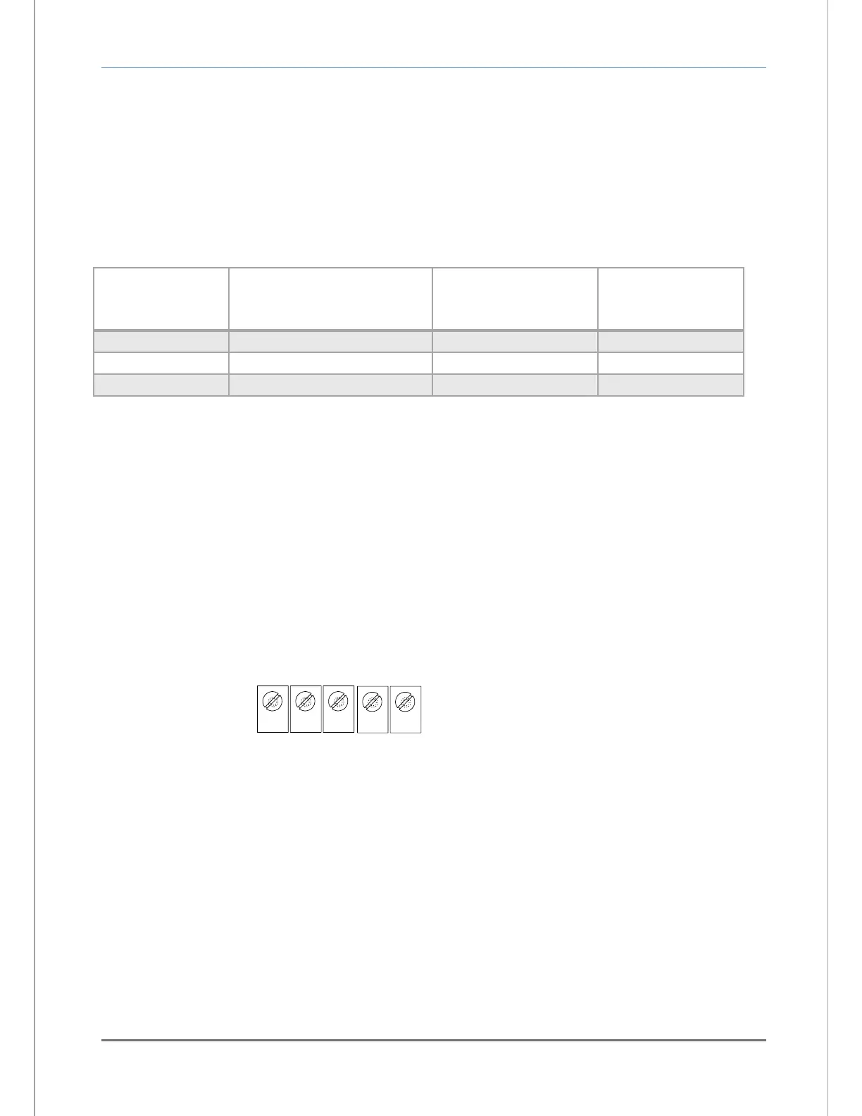
VAC POWER INPUT,
90-264 VAC, 47-63 Hz
VDC POWER INPUT,
11-18 VDC / 20-30 VDC
1 3
TB1
GND
5
VDC+
2 4
COM
GND
AC-N
AC-L
- or -
* Refer to Appendix C - Factory Configuration for the
correct DC voltage to use with your unit
Fig. 15, terminal block TB1