5.1.2.10.8 Relays disabled after CAL/Setup
This setting determines the time that relays will be held in their last state before returning to Run
mode from the control panel or service port user menus. The relays disabled time may be set
anywhere from 0 to 14,400 seconds. This setting is accessed from the Alarm Relay Setup Menu by
typing “8” or “S” on the RS-232 terminal.
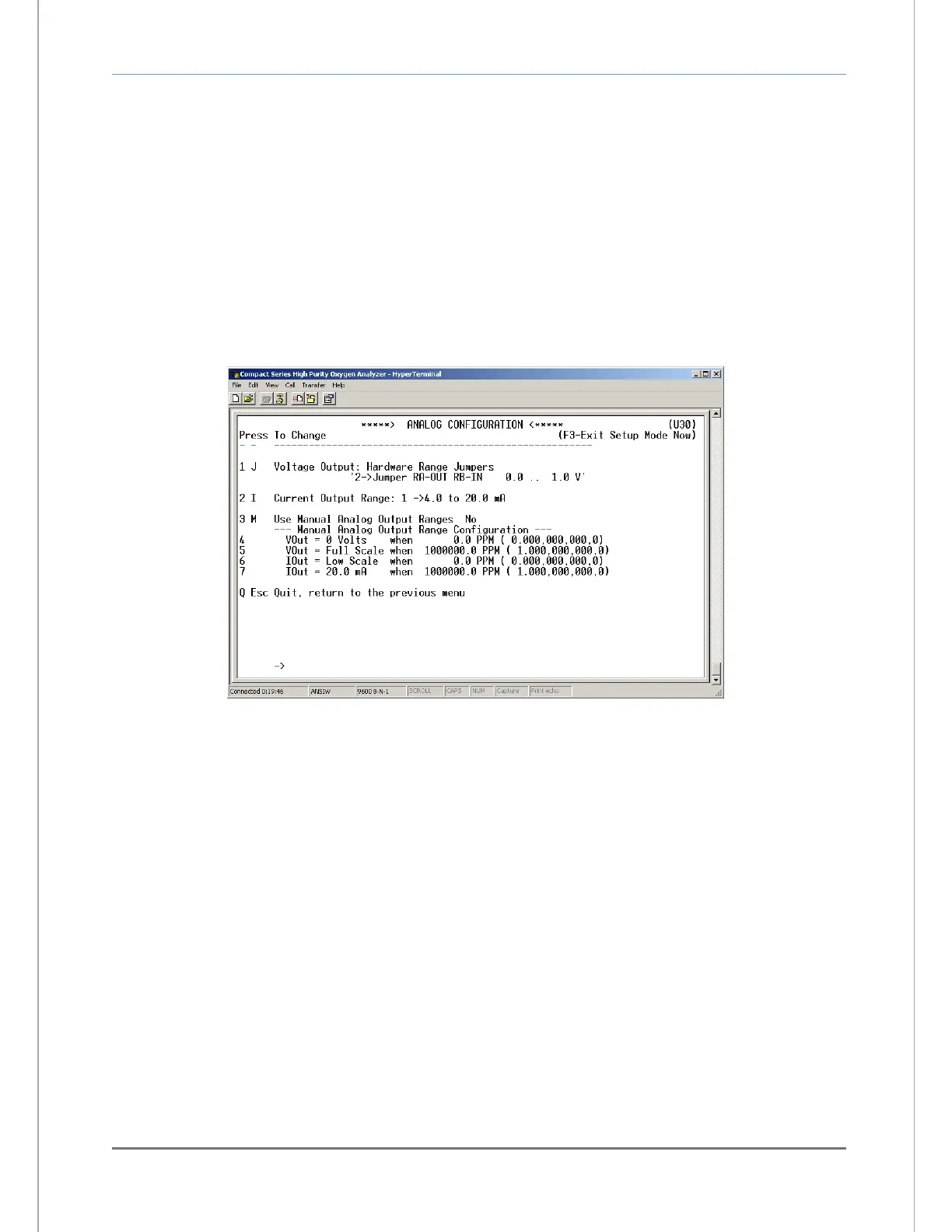
5.1.2.10.9 (U30) Analog output setup menu
The RS-232 Analog Output Setup menu U30 (Figure 24) provides access to all of the settings
related to the Analog Voltage Output (TB3-Pin 5, TB3-Pin 6) and Analog Current Output (TB3-Pin
7, TB3-Pin 8). It is accessed from the Setup Main Menu by typing “3” or “A” on the RS-232
terminal. To navigate backwards, use the <Esc> or “Q” key on the RS-232 terminal.
5.1.2.10.10 Analog voltage output range
This menu sets the Analog Voltage Output full-scale value. It may be set to 0 (0-5 VDC minimum to
full scale), 1 (0-10 VDC minimum to full scale) or 2 (0-1 VDC minimum to full scale). This setting
must match the RA and RB hardware jumper settings on the bottom of the main CPU PCB (section
4.1.3). This menu is accessed from the Analog Output Setup menu by typing “1” or “J” on the RS-
232 terminal.
5.1.2.10.11 Analog current output range
This menu sets the Analog Current Output range. It may be set to 0 (0-20mA minimum to full
scale), or 1 (4-20mA minimum to full scale). This menu is accessed from the Analog Output Setup
menu by typing “2” or “I” on the RS-232 terminal.
5.1.2.10.12 Use manual analog output ranges
This menu is used to enable manual override of Analog output mapping to display range, and to
force minimum and maximum Analog outputs to absolute Oxygen measurement values. This menu
is accessed from the Analog Output Setup menu by typing “3” or “M” on the RS-232 terminal.