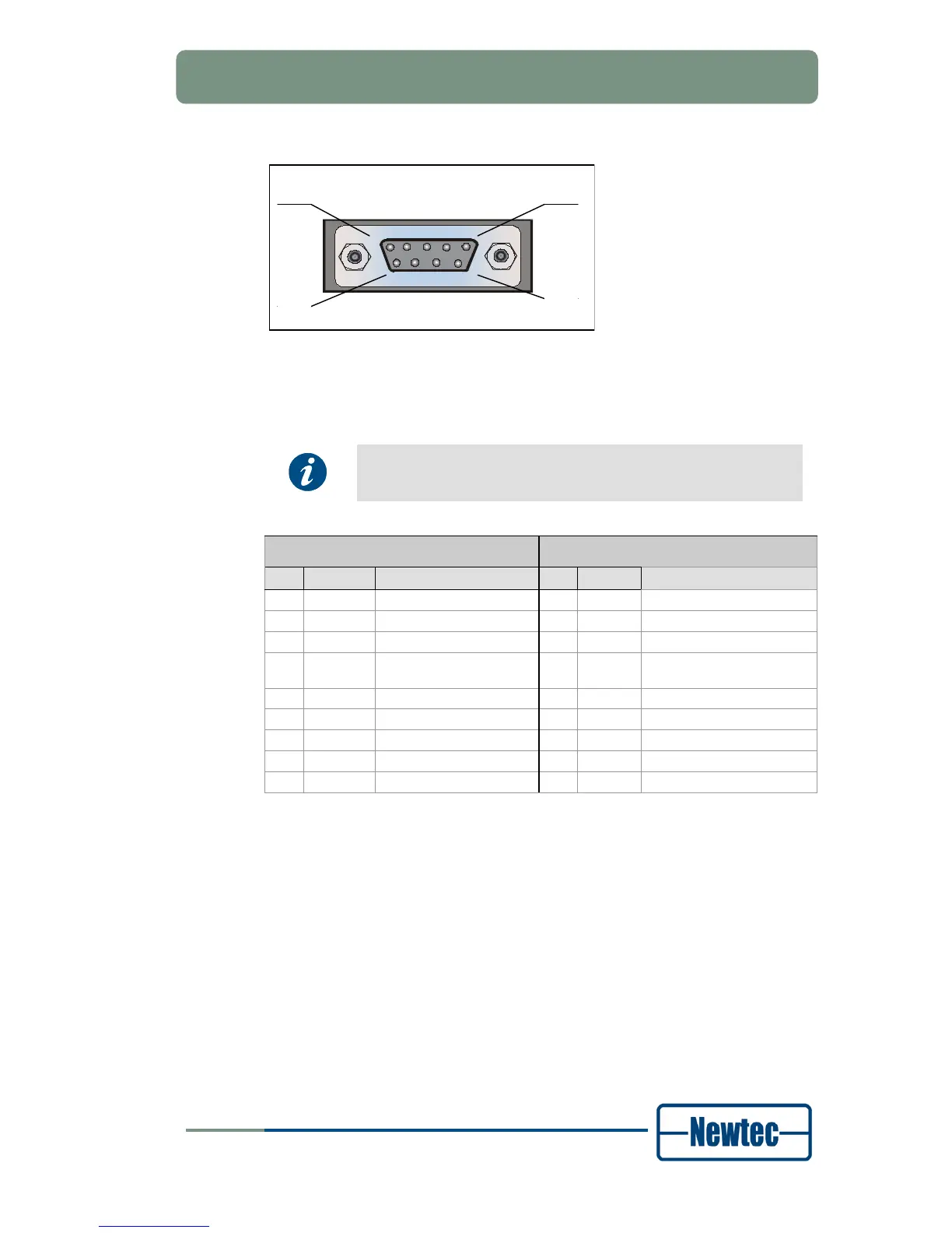
Figure 8 - Serial Monitoring and Control Connector
The modulator contains the hardware for the RS485 and RS232 interface.
Select the type of serial interface via the front panel or via the
GUI, but not via the serial port itself.
RS485 RS232
Pin Name Function Pin Name Function
1 GND Shield ground 1 GND Shield ground
2 Not connected 2 Rx-D Receive Data (input)
3 Tx-A Send Data A (input) 3 Tx-D Transmit Data (output)
4 Rx-A Receive Data A (output) 4 DTR Data Terminal Ready
(output)
5 GND Signal ground 5 GND Signal ground
6 Rx-B Receive Data B (output) 6 Not connected
7 Not connected 7 RTS Request to send (output)
8 Not connected 8 CTS Clear to send (input)
9 Tx-B Send Data B (input) 9 Not connected
Table 1 - Pin Configuration