SHAPING THE FUTURE SATELLITE OF COMMUNICATIONS
3.2.2 Sub Back Panel Descriptions
In this section the optional back panels are listed. Depending on the options
ordered a combination of back panels is used.
The different combinations per ordering option are described in the following
section 3.2.3.
The connector REF OUT is used for option GR01 or GR02.
When one of these options is selected the REF OUT connector is
available on the first sub back panel that enables this option.
In all other sub back panels this option is not used.
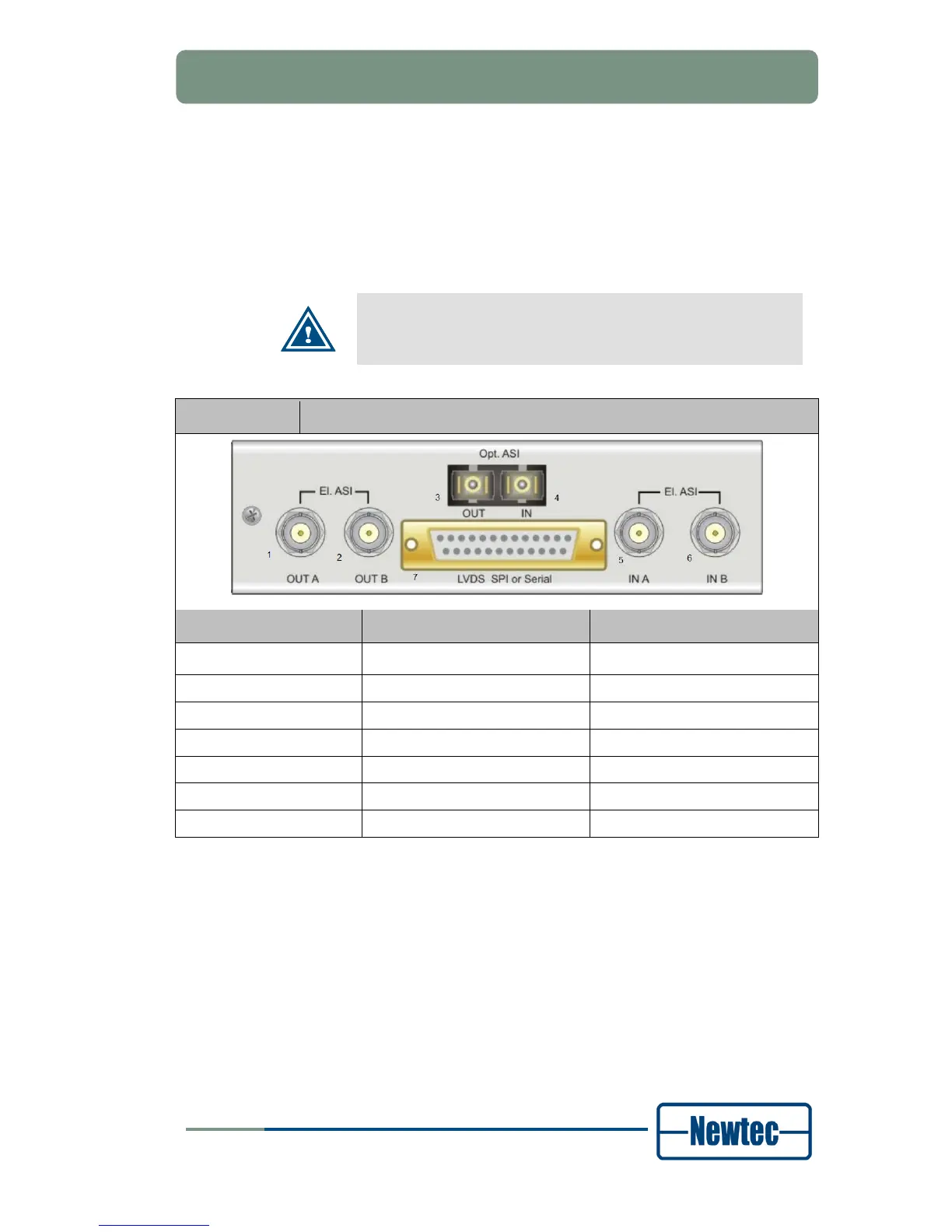
Back Panel 01 / Description
Connector Technical Specifcations Signalling Type
1. El. ASI OUT A BNC (Female) 50 Ohm Output signal
2. El ASI OUT B BNC (Female) 50 Ohm Output signal
3. Opt ASI OUT Optical connector ASI
4. Opt ASI IN Optical connector ASI
5. El. ASI IN A BNC (Female) 50 Ohm ASI
6. El. ASI IN B BNC (Female) 50 Ohm ASI
7. LVDS SPI or Serial Sub-D (Female) 25 Pins