Page 54/79 GEO M10 HARDWARE SETUP PROCEDURE
Required items
- 1 or 2 hoists (not provided).
- 2 x VNT-BUMPM10
- 1 x VNT-EXBARM10 for extended positive and negative bumper angles
IMPORTANT
When flying MSUB15 & GEO M10 cluster, VNT-BUMPM10 must be set at 0°
- If cluster is flown from a single point, select rigging point position from NS1 design
- If cluster is flown from 2 points, bumper must be maintained horizontal in its definitive
position as well as when lifting or lowering the cluster
IMPORTANT
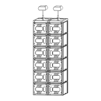
Maximum quantity for flown vertical cluster with VNT-BUMPM10 is:
N
GEOM10
+ 1.5*N
MSUB15
<= 12
Please check NS1 for mechanical Safety Working Load and acoustic computations.
IMPORTANT
Motor hoist must be rated to support entire cluster weight. Please check configuration
in NS1 for proper motor hoist rating
Procedure
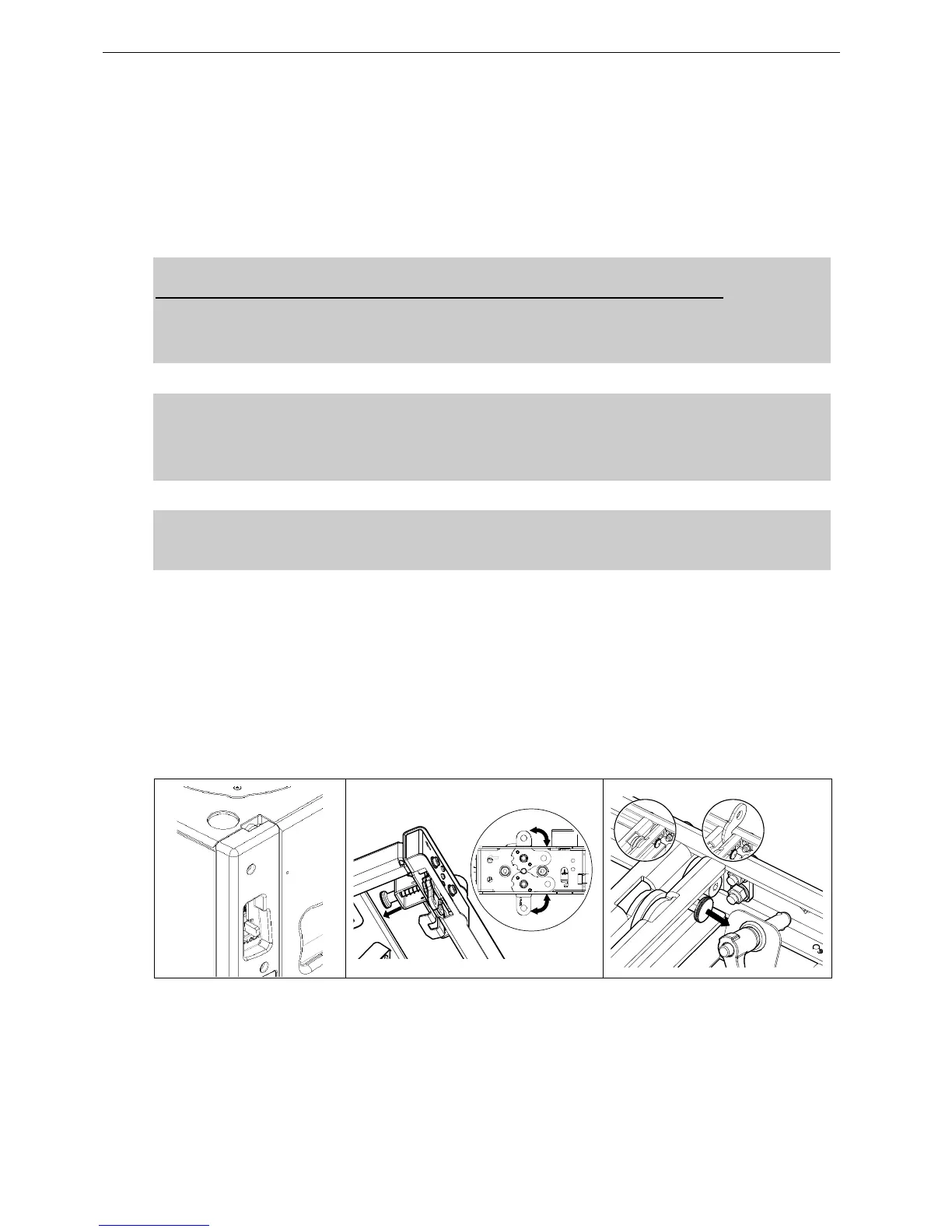
- Position first MSUB15 and unlock front and rear rigging points
- Pull the bumper front latches, rotate the lower links so that connection points are double leg and
release the latches.
- Position bumper on top of first MSUB15 and lock front and rear points to the bumper with 2 BL820
quick release pins.
- If flying with bumper only, pull front and rear center latches, and release front and rear bumper
connecting points.
 Loading...