GEO M10 HARDWARE SETUP PROCEDURE Page 57/79
Subsequent GEO M10s
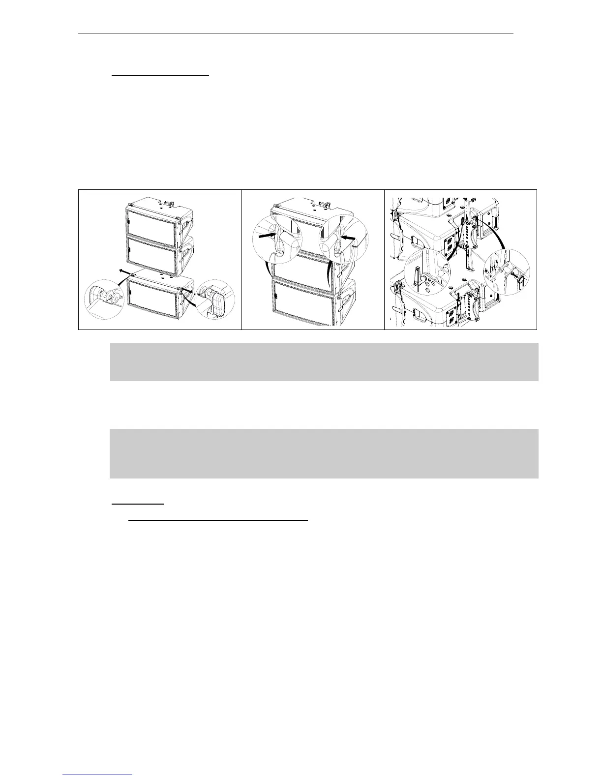
- Lift assembly to sufficient height in order to connect a second GEO M10;
- Position second GEO M10 cabinet with AutoRig
TM
in automatic lock position, and lock front points to
first GEO M10
- Unlock GEO M10 link bar
- Pull the latch to engage the guide in GEO M10 rear slot.
- Adjust the angle by inserting quick release pin BL820 in proper hole.
- Connect subsequent GEO M10 cabinets as with second.
IMPORTANT
Ensure that bumper quick release pins are properly locked into GEO M10, and that all
AutoRig
TM
and rear connecting points are locked
- Lift cluster to NS-1 defined rigging height, secure cluster horizontally to prevent it from rotating;
- Secure bumper with secondary safety steel.
IMPORTANT
The requirements for secondary safety systems vary with territories. However, the
secondary safety steel MUST have a SWL equivalent or greater than that of the rigging
system.
Disassembly
- While holding GEO M10 to be dismounted, pull AutoRig
TM
on both sides and hold the side knob
(AutoRig
TM
remains in the open position).
- Remove the rear quick release pin BL820
- Unlock the GEO M10 link bar by pulling the latch.
- Remove GEO M10
 Loading...