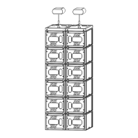
- Once all MSUB15 are off the ground, position second VNT-BUMPM10 below last MSUB15
- Pull bottom bumper front latches, and rotate the upper links so that single leg, and release the
latches
- Unlock last MS15SUB top front and rear rigging points
- Connect bottom bumper to last MSUB15 by locking front and rear rigging points
GEO M10 Left
- Position first GEO M10 below bottom bumper so that Autorig
TM
is at the bottom
- Pull the bottom bumper front latches, rotate the lower links so that connection points are double leg
and release the latches.
- Position first GEO M10 below bottom bumper and lock front points to the bumper with 2 BL820 quick
release pins.
- Connect the bumper link bar at required angle (selection from -12° to +12° in 3° steps) to GEO M10
rear rigging plate (hole marked “bumper”) and lock with the quick release pin BL0825.
GEO M10 Right
- Position first GEO M10 so that Autorig
TM
is at the top and set in automatic lock position
- Pull the bumper front latches, rotate the lower links so that connection points are single leg and
release the latches.
- Position bumper on top of first GEO M10, front points will lock automatically
- Connect the bumper link bar at required angle (selection from -12° to +12° in 3° steps) to GEO M10
rear rigging plate (hole marked “bumper”), and lock with the quick release pin BL0825.
 Loading...