NXAMP4x1
12
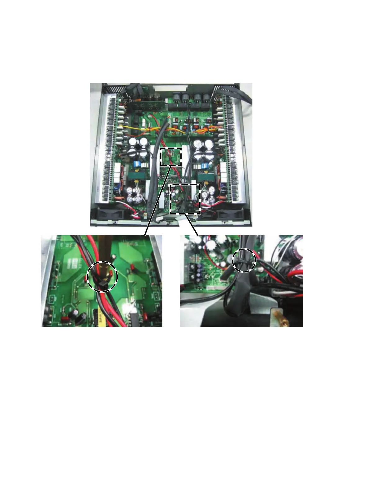
g) Fasten these wires (WK17900, WK17910 and WK94710) with a cord holder to the hexagonal spacer. (Fig. 21)
h) Bend the wire (WK14200) and wire (WK16820) connected to the connector (CN317), and fasten the wires (WK14210, WK16820
x 2 and WK14200) with a cord holder. (Fig. 21)
Note: When connecting the connector assembly to the CONTROL circuit board, confirm that the connector housing pin
number of the connector assembly is the same as the connector pin number of the circuit board.
i) Fasten the wires (WK02080, WK90770) with a cord holder at the hole of the RS232-GPI circuit board. (Fig. 22)
j) Fasten the wires (WK02080, WK90770 and WK02070) with a cord holder at the hole of the enclosure.
Fasten the wires (WK90790, WK17110) with a cord holder at the hole of the enclosure. (Fig. 22)
k) Fasten the wires (WK90790, WK17110) with a cord holder at the hole of the OPT-AN circuit board. Then connect the flat cable
(WK02120). (Fig. 22)
l) Fasten the wires (WK02080, WK90770, WK90790, WK17110 and WK02070) with a cord holder at the position close to the
OPT-AN circuit board. (Fig. 22)
m) Bend the wire (WK02090), and fasten the wires (WK02090, WK68760 and WK68770) with a cord holder. (Fig. 22).
n) Bend the flat cable as shown in the figure. (Fig. 22)
Fig. 21
g)
h)

 Loading...


