NXAMP4x1
14
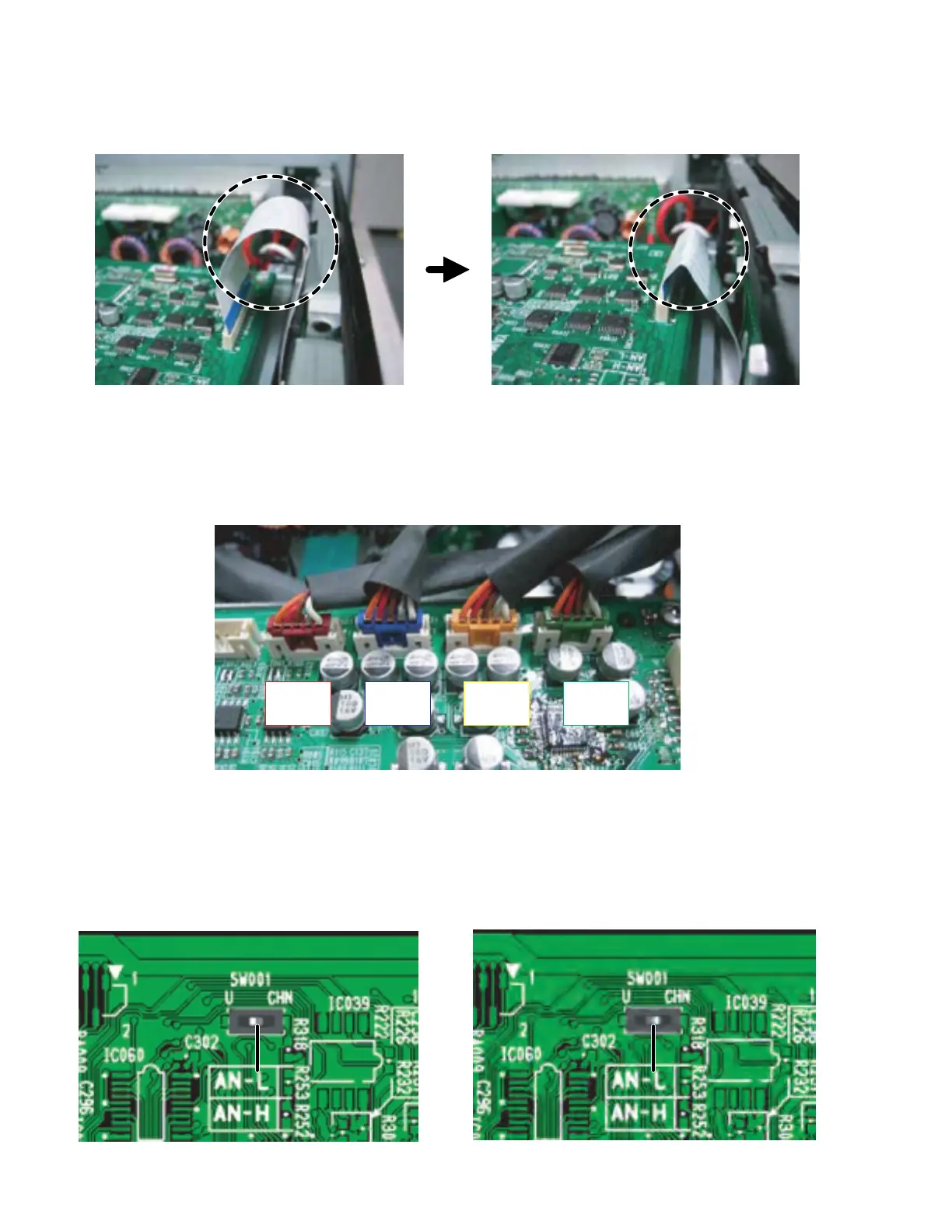
Switch knob Switch knob
9. Change of the destination
Set the knob position of the switch SW001 on the CONTROL circuit board as shown in the figure below. (Fig. 26, 27)
8. Color of the connectors connected to the connector CN012-CN015
Connect the connector assembly from the PA unit to the CONTROL circuit board as shown in the figure below. (Fig. 25)
Fig. 25
Fig. 26 Fig. 27
U destination CHN destination
o) Bend the flat cable to avoid touching the top cover. (Fig. 23, 24)
Fig. 23 Fig. 24
CN012
RED
CN013
BLUE
CN014
YELLOW
CN015
GREEN

 Loading...


