NXAMP4x1
18
[380]: Bind Head Tapping Screw-S 3x6 MFZN2W3 (--)
[400]: Bind Head Tapping Screw-S 3x6 MFZN2W3 (--)
[410]: Bind Head Tapping Screw-S 3x6 MFZN2B3 (--)
[430]: Bind Head Tapping Screw-S 3x6 MFZN2W3 (--)
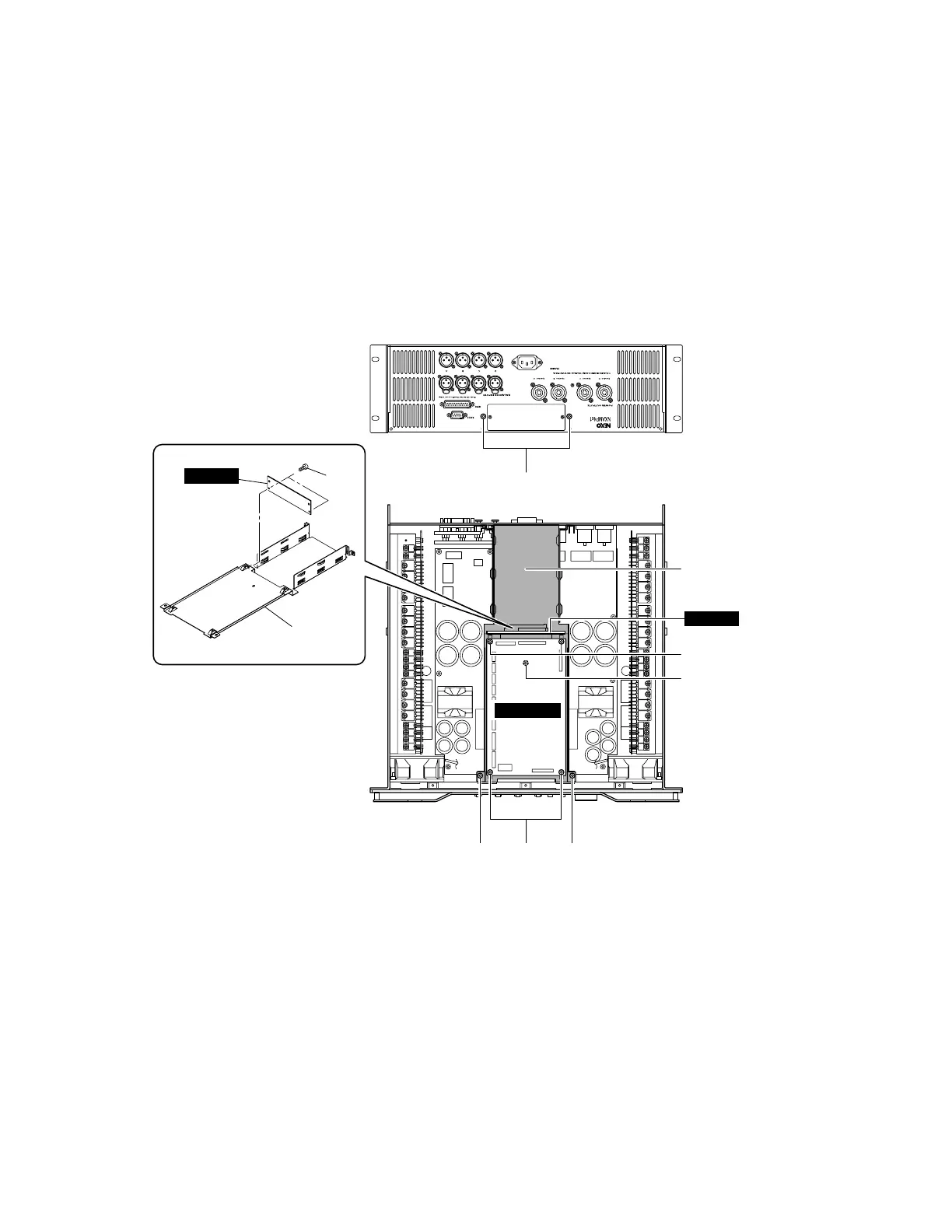
(Fig. 2)
2. CONTROL Circuit Board, OPT angle and OPT-AN Circuit Board
(Time required: about 10 minutes)
2-1. Remove the top cover. (See procedure 1.)
2-2. Remove the four (4) screws marked [430]. (Fig. 2)
2-3. Disconnect the connector assemblies from other units connected to the CONTROL circuit board. (Fig. 2)
2-4. The CONTROL circuit board can then be removed. (Fig. 2)
2-5. Remove the three (3) screws marked [400] and the two (2) screws marked [410]. (Fig. 2)
2-6. Remove the OPT angle with the OPT-AN circuit board. (Fig. 2)
2-7. Remove the two (2) screws marked [380]. (Fig. 2)
2-8. The OPT-AN circuit board can then be removed. (Fig. 2)
OPT angle
OPT angle
[430][400] [400]
[410]
[400]
[380]
[430]
CONTROL
OPT-AN
OPT-AN

 Loading...


