NXAMP4x1
19
[277]: Plastic Rivet NRP-345 (--)
[280]: Flat Head Tapping Screw-B 3x8 MFZN2B3 (--)
[285]: Bind Head Tapping Screw-S 3x6 MFZN2W3 (--)
[290]: Bind Head Tapping Screw-B 3x8 MFZN2B3 (--)
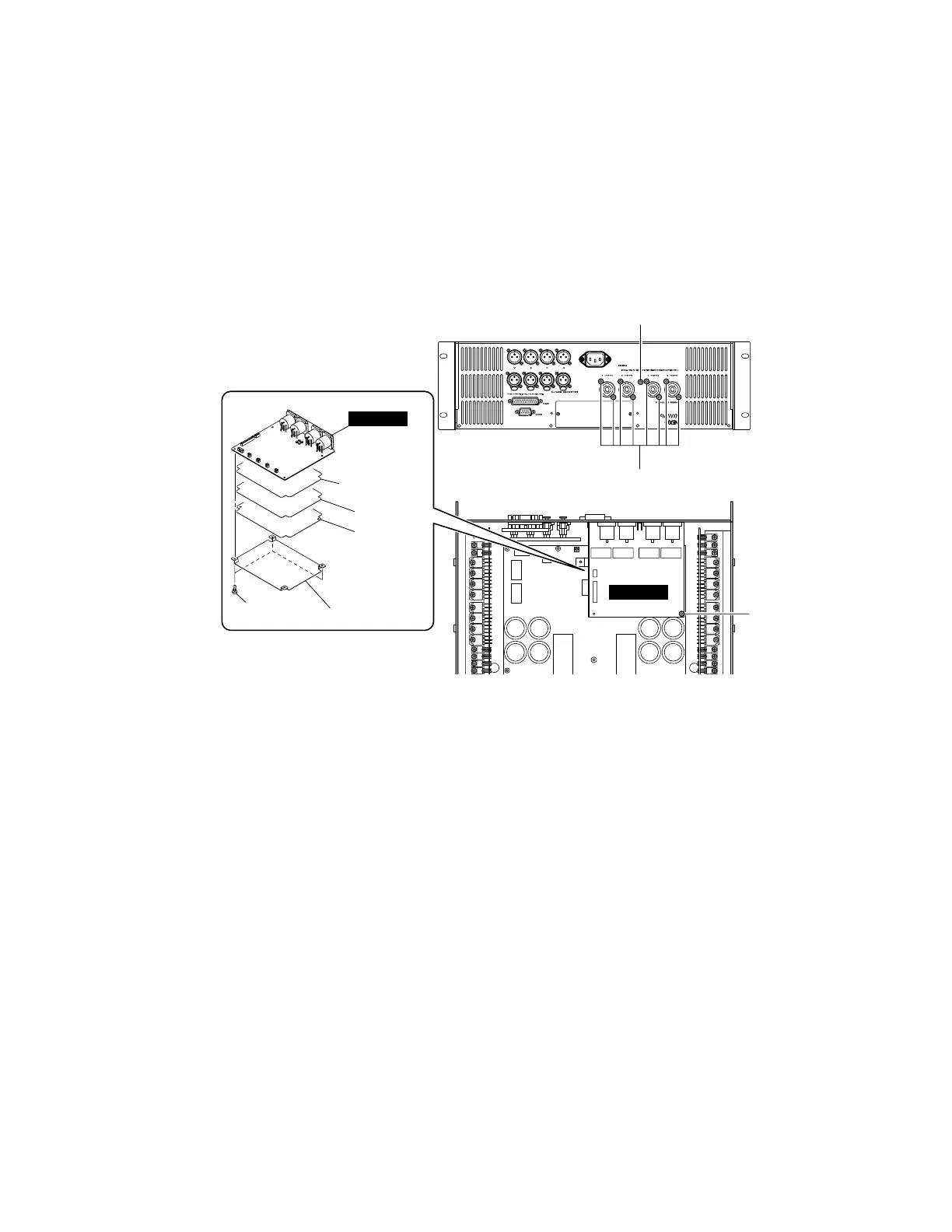
(Fig. 3)
3. OUTANL Circuit Board (Time required: about 15 minutes)
3-1. Remove the top cover. (See procedure 1.)
3-2. Remove the CONTROL circuit board and the OPT angle. (See procedure 2.)
3-3. Remove the eight (8) screws marked [280], the one (1) screw marked [290] and the one (1) screw marked [285]. (Fig. 3)
3-4. Disconnect the connector assemblies from other units connected to the OUTANL circuit board. (Fig. 3)
3-5. The OUTANL circuit board with the two (2) insulation sheets and the two (2) shields can then be removed. (Fig. 3)
3-6. Remove the three (3) plastic rivets marked [277]. (Fig. 3)
3-7. Remove the insulation sheet 1, the shield 1, the shield 2 and the insulation sheet 2 from the OUTANL circuit board. (Fig. 3)
[280]
[290]
[285]
[277]
OUTANL
OUTANL
Insulation sheet 1
Insulation
sheet 2
Shield 1
Shield 2

 Loading...


