NXAMP4x1
20
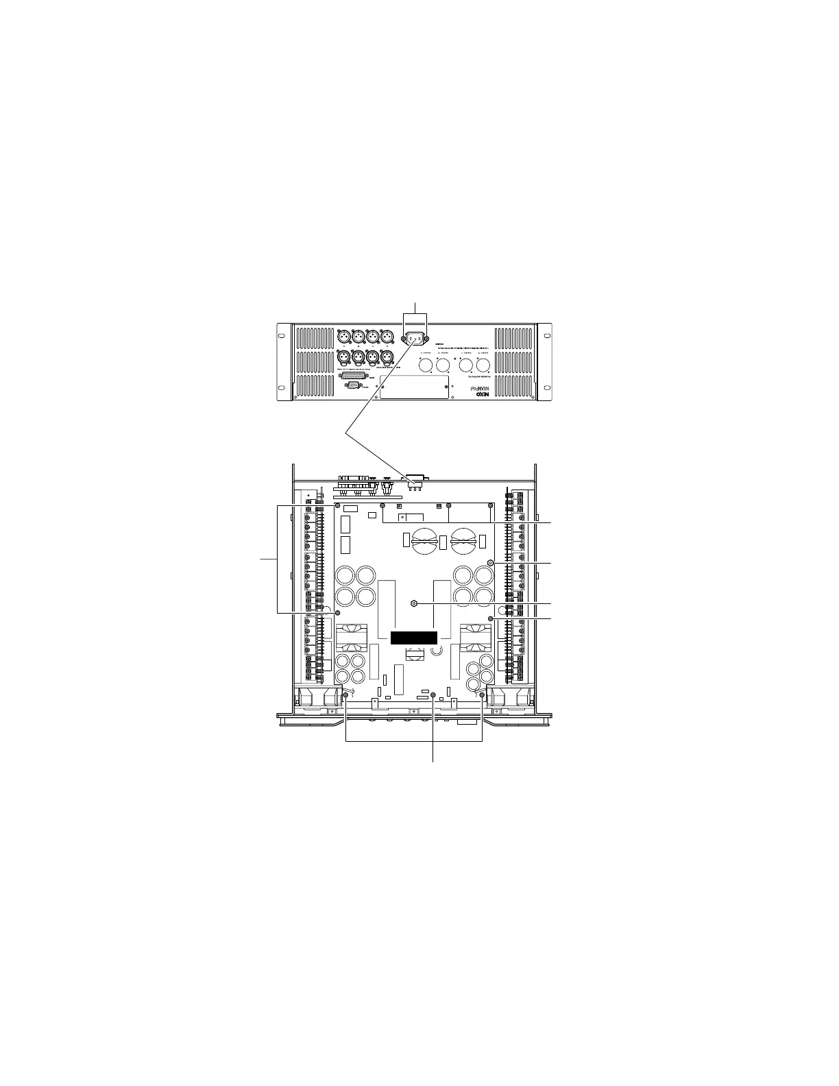
4. PSANL Circuit Board (Time required: about 20 minutes)
4-1. Remove the top cover. (See procedure 1.)
4-2. Remove the CONTROL circuit Board and the OPT angle. (See procedure 2.)
4-3. Remove the OUTANL Circuit Board. (See procedure 3.)
4-5. Remove the two (2) screws marked [150], and remove the ACPS connector assembly. (Fig. 4)
4-6. Remove the nine (9) screws marked [100], the one (1) hexagonal spacers marked [90] and the one (1) hexagonal spacer
marked [95]. (Fig. 4)
4-7. Disconnect the connector assemblies from other units connected to the PSANL circuit board. (Fig. 4)
4-8. The PSANL circuit board can then be removed. (Fig. 4)
[90]: Hexagonal Spacer H=89 B=5.5 (--)
[95]: Hexagonal Spacer H=41 B=5.5 (--)
[100]: Bind Head Tapping Screw-S 3x6 MFZN2W3 (--)
[150]: Flat Head Tapping Screw-B 3x8 MFZN2B3 (--) (U destination)
[150]: Bind Head Tapping Screw-B 3x8 MFZN2B3 (--) (O destination)
(Fig. 4)
ACPS connector assembly
[100]
[150]
[90]
[100]
[95]
[100]
PSANL
[100]

 Loading...


