NXAMP4x1
21
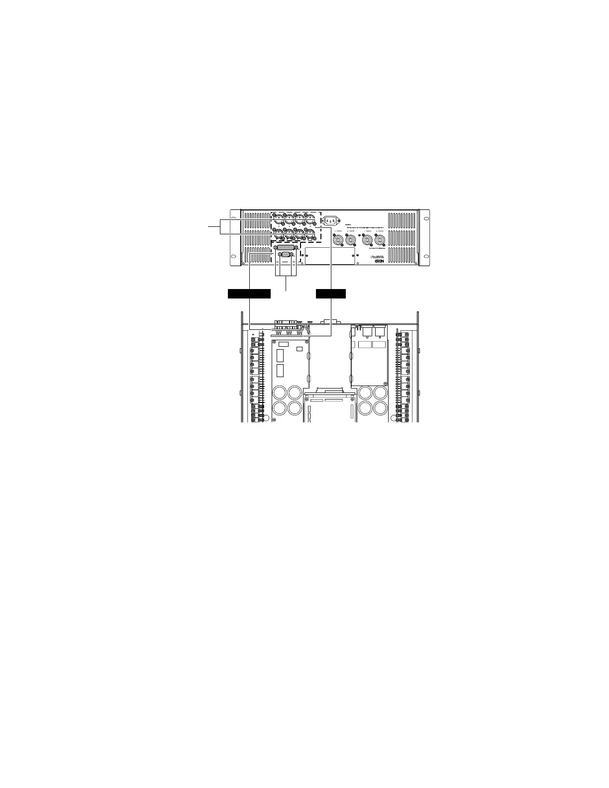
5. INANL Circuit Board
(Time required: about 7 minutes)
5-1. Remove the top cover. (See procedure 1.)
5-2. Remove the sixteen (16) screws marked [70]. (Fig. 5)
5-3. Disconnect the connector assembly from other unit con-
nected to the INANL circuit board. (Fig. 5)
5-4. The INANL circuit board can then be removed. (Fig. 5)
[70]: Bind Head Tapping Screw-B 2.6x8 MFZN2B3 (--)
[330]: Hexagonal Lock Screw (--)
(Fig. 5)
[330]
RS232-GPI
[70]
INANL
6. RS232-GPI Circuit Board
(Time required: about 7 minutes)
6-1. Remove the top cover. (See procedure 1.)
6-2. Remove the four (4) hexagonal lock screws marked
[330]. (Fig. 5)
6-3. Disconnect the flat cable from other unit connected to
the RS232-GPI circuit board. (Fig. 5)
6-4. The RS232-GPI circuit board can then be removed.
(Fig. 5)

 Loading...


