NXAMP4x1
23
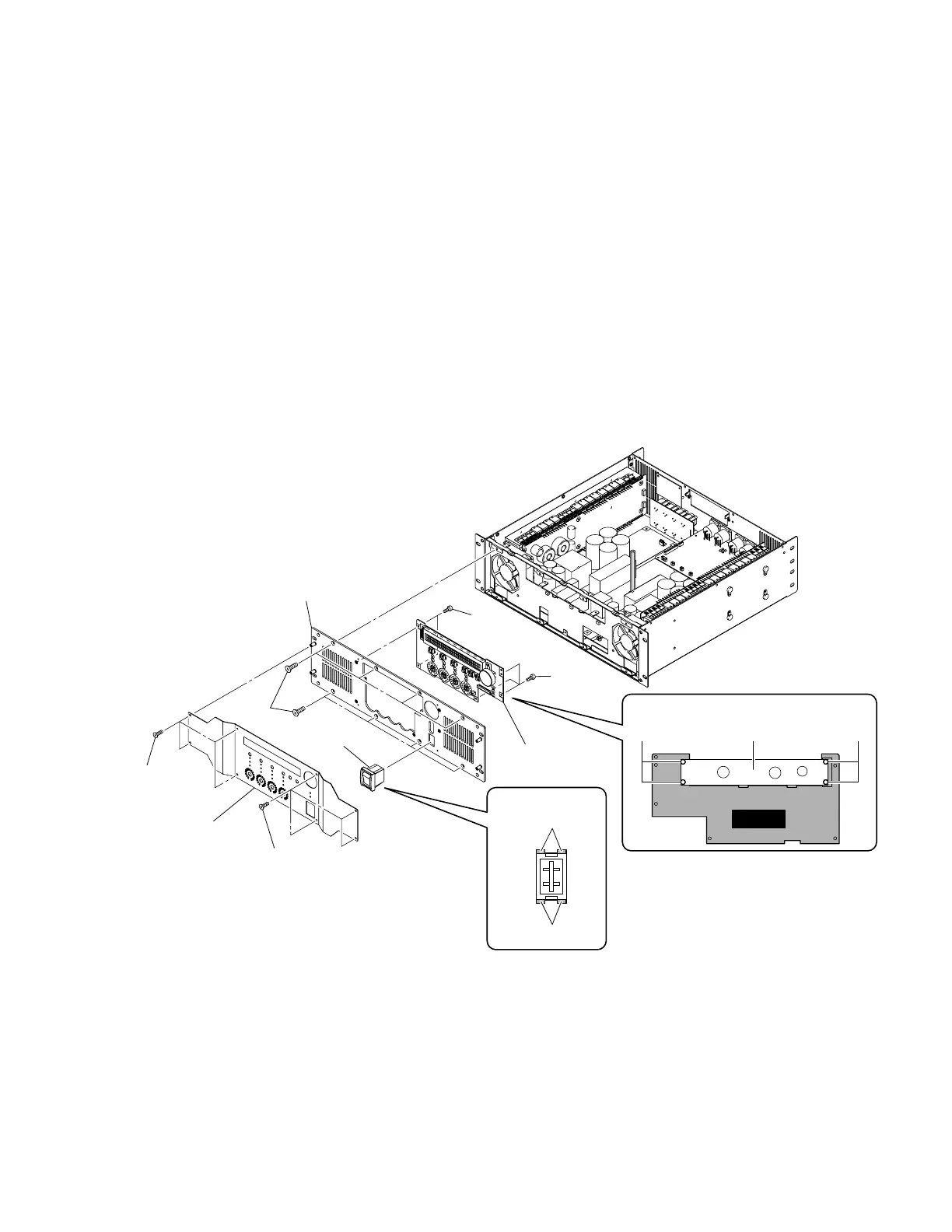
10. PN-AN Circuit Board
(Time required: about 10 minutes)
10-1. Remove the top cover. (See procedure 1.)
10-2. Remove the front panel assembly. (See procedure 9.)
10-3. Remove the five (5) screws marked [500]. (Fig. 7)
10-4. Remove the LCD assembly. (Fig. 7)
10-5. Remove the four (4) nylon rivets [40]. (Fig. 7)
10-6. The PN-AN circuit board and the LCD unit can then be
separated. (Fig. 7)
9. Front Panel Assembly
(Time required: about 6 minutes)
9-1. Remove the top cover. (See procedure 1.)
9-2. Remove the CONTROL circuit Board and the OPT
angle. (See procedure 2.)
9-3. Remove the eight (8) screws marked [590]. (Fig. 7)
9-4. Remove the front panel 2. (Fig. 7)
9-5. Disconnect the connector of the power switch assem-
bly connected to the PSANL circuit board. (Fig. 7)
9-6. Remove the eight (8) screws marked [510]. (Fig. 7)
9-7. Disconnect the flat cable from other unit connected to
the PN-AN circuit board. (Fig. 7)
9-8. The front panel assembly can the be removed. (Fig. 7)
[40]: Nylon Rivet (--)
[500]: Bind Head Screw 3x4 MFZN2B3 (--)
[510]: Flat Head Screw 4x8 MFZN2B3 (--)
[590]: Bind Head Tapping Screw-S 3x6 MFZN2B3 (--)
(Fig. 7)
[500]
[500]
[40]
[510]
[590]
[590]
Front panel assembly
Front panel 2
Power switch
Power switch
HookHookHook
Hook
LCD assembly
LCD assembly
LCD unit
PN-AN
[40]

 Loading...


