NXAMP4x1
24
12. Right DC fan (Time required: about 15 minutes)
12-1. Remove the top cover. (See procedure 1.)
12-2. Remove the CONTROL circuit board and the OPT
angle. (See procedure 2.)
12-3. Remove the front panel assembly. (See procedure 9.)
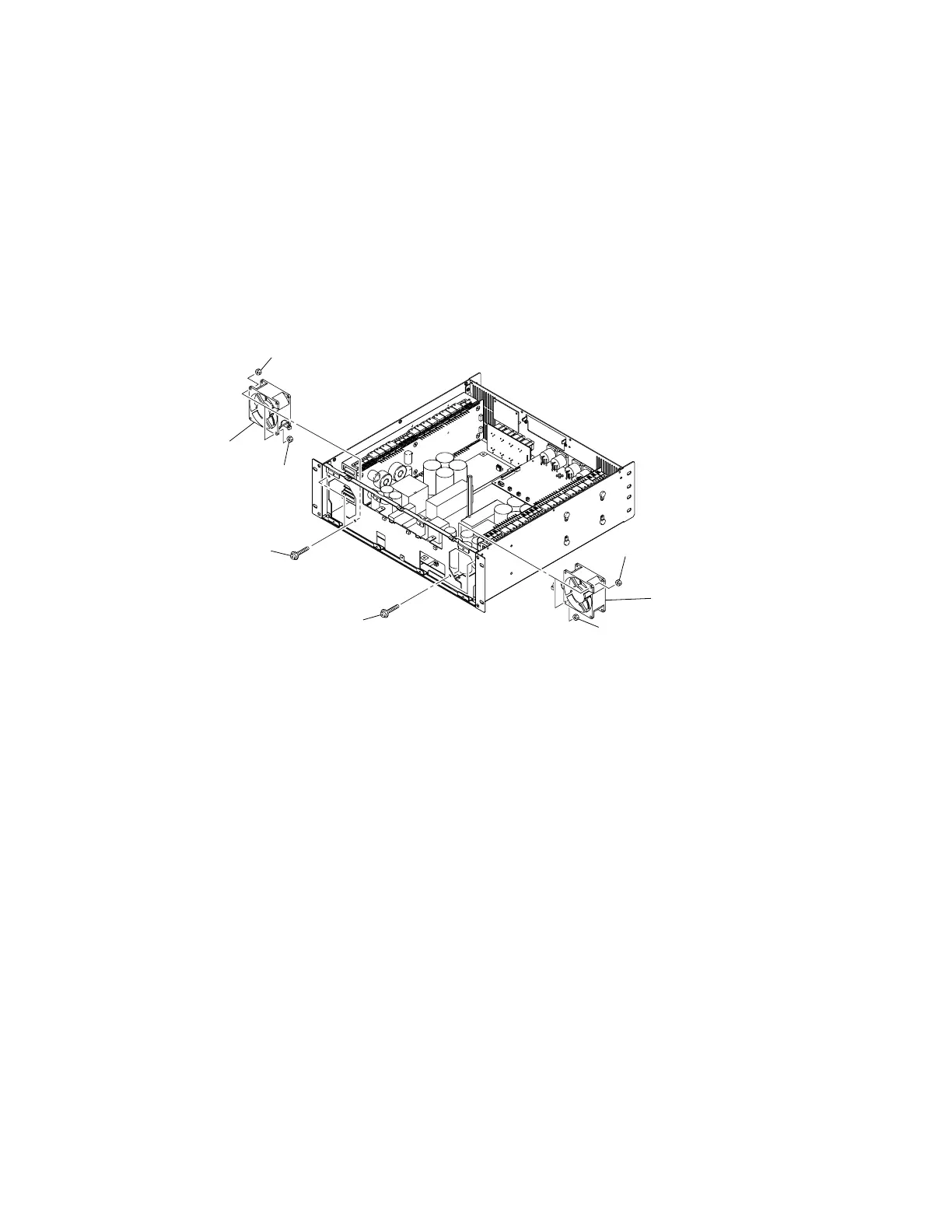
12-4. Remove the two (2) screws marked [40B] and the two
(2) hexagonal nuts marked [50B]. (Fig. 8)
12-5. Disconnect the connector of the right DC fan connected
to the PSANL circuit board. (Fig. 8)
12-6. The right DC fan can then be removed. (Fig. 8)
11. Left DC Fan (Time required: about 15 minutes)
11-1. Remove the top cover. (See procedure 1.)
11-2. Remove the CONTROL circuit board and the OPT
angle. (See procedure 2.)
11-3. Remove the front panel assembly. (See procedure 9.)
11-4. Remove the two (2) screws marked [40A] and the two
(2) hexagonal nuts marked [50A]. (Fig. 8)
11-5. Disconnect the connector of the left DC fan connected
to the PSANL circuit board. (Fig. 8)
11-6. The left DC fan can then be removed. (Fig. 8)
[40A]: Bind Head Screw 4x35 MFZN2W3 SP (--)
[40B]: Bind Head Screw 4x35 MFZN2W3 SP (--)
[50A]: Hexagonal Nut M4 #1 (--)
[50B]: Hexagonal Nut M4 #1 (--)
(Fig. 8)
[40B]
[50B]
DC fan
[50B]
[40A]
[50A]
DC fan
[50A]

 Loading...


