NXAMP4x1
25
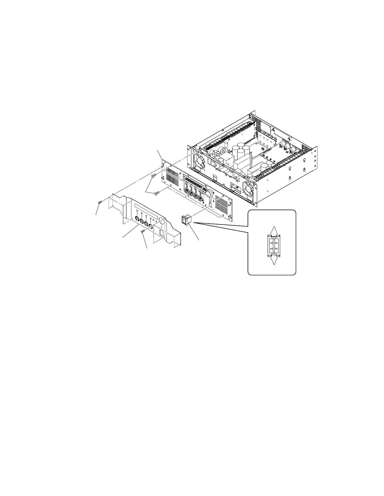
13. Power switch (Time required: about 15 minutes)
13-1. Remove the top cover. (See procedure 1.)
13-2. Remove the CONTROL circuit Board and the OPT angle. (See procedure 2.)
13-3. Disconnect the connector of the power switch assembly connected to the PSANL circuit board. (Fig. 9)
13-4. Remove the front panel assembly. (See procedure 9.)
13-5. Release the four (4) hooks of the power switch, and remove the power switch from the front panel assembly. (Fig. 9)
(Fig. 9)
[510]
[590]
[590]
Front panel assembly
Front panel 2
Power switch
Power switch
Hook
Hook
Hook
[510]: Flat Head Screw 4x8 MFZN2B3 (--)
[590]: Bind Head Tapping Screw-S 3x6 MFZN2B3 (--)

 Loading...


