NI cDAQ-9178/9174 User Guide and Specifications 40 ni.com
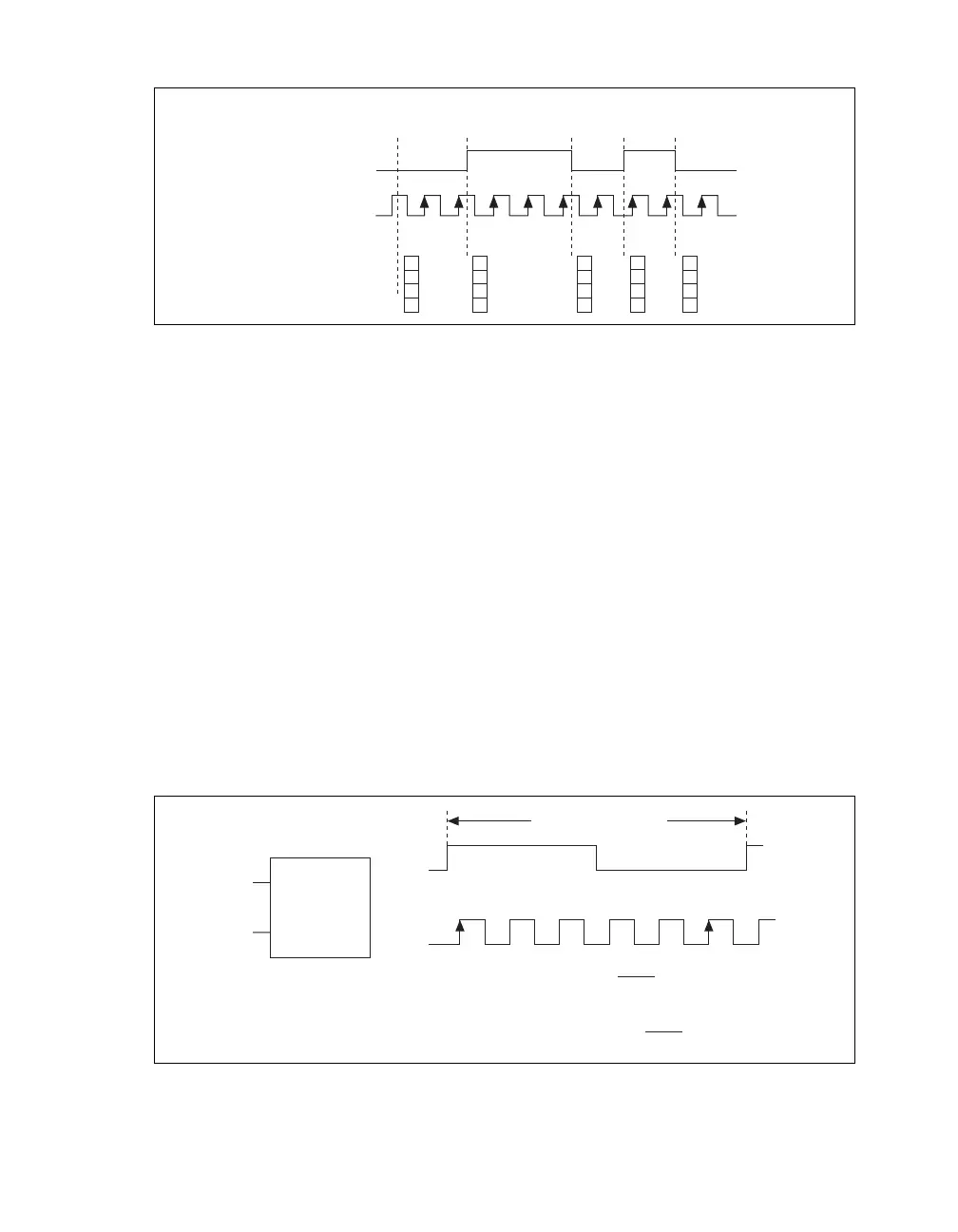
Figure 30 shows an example of an implicit buffered semi-period measurement.
Figure 30. Implicit Buffered Semi-Period Measurement
For information about connecting counter signals, refer to the Default Counter/Timer Routing section.
Frequency Measurement
You can use the counters to measure frequency in several different ways. Refer to the following sections
for information about NI cDAQ-9178/9174 frequency measurement options:
• Low Frequency with One Counter
• High Frequency with Two Counters
• Large Range of Frequencies with Two Counters
• Sample Clocked Buffered Frequency Measurement
Low Frequency with One Counter
For low frequency measurements with one counter, you measure one period of your signal using a
known timebase.
You can route the signal to measure (fx) to the Gate of a counter. You can route a known timebase (fk)
to the Source of the counter. The known timebase can be an onboard timebase, such as 80 MHz
Timebase, 20 MHz Timebase, or 100 kHz Timebase, or any other signal with a known rate.
You can configure the counter to measure one period of the gate signal. The frequency of fx is the inverse
of the period. Figure 31 illustrates this method.
Figure 31. Low Frequency with One Counter
1
2
3
1
3
3
SOURCE
GATE
Counter Value
Buffer
1 3
2
2
11
13
12
0
Counter
Armed
Starting
Edge
fx
fk
Gate
Source
123 … N
Single Period
Measurement
…
Period of fx =
N
Frequency of fx =
N
Interval Measured
fk
fk
fk
fx