Pipe dimensions and materials
Liquid pipeGas pipe
Ø9.52 mm (3/8")Ø15.88 mm (5/8")Pipe dimension
Flare - (3/8")Flare - (5/8")Connection
Copper quality SS-EN 12735-1 or
C1220T, JIS H3300
Material
0.8 mm1.0 mmMinimum material
thickness
Pipe connection
႑
Perform pipe installation with the service valves (QM35,
QM36) closed.
႑
HBS 16
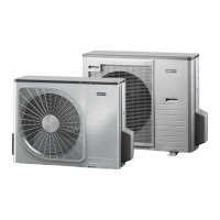
The image below, shows possible pipe outlets.
LEK
;/
;/
;/
;/
;/
;/
႑
Ensure that water or dirt does not enter the pipes.
႑
Bend the pipes with as large a radius as possible (at least
R100~R150). Do not bend a pipe repeatedly. Use a
bending tool.
႑
Connect the flare connector and tighten to the following
torque. Use the "Tightening angle" if a torque wrench
is not available.
Recommen-
ded tool
length (mm)
Tightening
angle (°)
Tightening
torque (Nm)
Outer diamet-
er, copper
pipe (mm)
20030~4534~42Ø9.52
30015~2068~82Ø15.88
NOTE
Gas shielding must be used when soldering.
Flare connections
Expansion:
A
A (mm)Outer diameter, copper pipe (mm)
13.2Ø9.52
19.7Ø15.88
Ejection:
B
B, with a conven-
tional tool (mm)
B, with an R410A
tool (mm)
Outer diameter,
copper pipe (mm)
0.7~1.30~0.5Ø9.52
Ø15.88
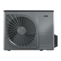
NIBE™ SPLIT24
For the Installer
Pipe installation

 Loading...