29NIBE BA-SVM 10-200
6 Electrical connections
General information
All electrical equipment, except the outdoor temper-
ature sensor, room sensor and current sensors are
already connected at the factory.
• Disconnect the power supply of the indoor unit
before insulation testing the building wiring.
• If the house is equipped with a residual-current de-
vice, BA-SVM 10-200 should be equipped with a
separate residual current breaker.
• For the indoor unit wiring diagram, see section
“Electrical wiring diagram”.
• Communication and sensor cables must not be
laid close to high-voltage cables.
• The minimum cross section of the communica-
tion and sensor cables to external connections
must be 0.5 mm² with a length of up to 50 m, for
example EKKX, LiYY or equivalent.
• The power supply cable should be dimensioned
according to the current standards.
• To route the cables to BA-SVM 10-200, use cable
grommet UB1 (marked in the drawing). In UB1,
the cables are routed through the entire indoor
unit from the back to the front.
CAUTION
The switch (SF1) for the controller must not be set to
“I” or “ ” until the climate system has been filled
with heating medium and the central heating system
vented”. Otherwise, the thermal circuit breaker, ther-
mostat and the flow-through heater may be damaged.
CAUTION
Cut off the power using the circuit breaker before car-
rying out any servicing. Electrical installation must be
carried out in accordance with the current regulations
by a person with the proper authorisations and quali-
fications.
CAUTION
When SF1 is set to „ ” - the BA-SVM 10-200 unit
switches the QN10 valve to the central heating and
heating takes place according to thermostat BT30. Hot
water is not heated while the switch is set to „ ”.
CAUTION
If the system is operating at “ ” the temperature on
BT30 should be aligned with the operating tempera-
ture of the central heating system. If the temperature
set on the thermostat is too high, it can damage the
system.
Section 6 | Electrical connections
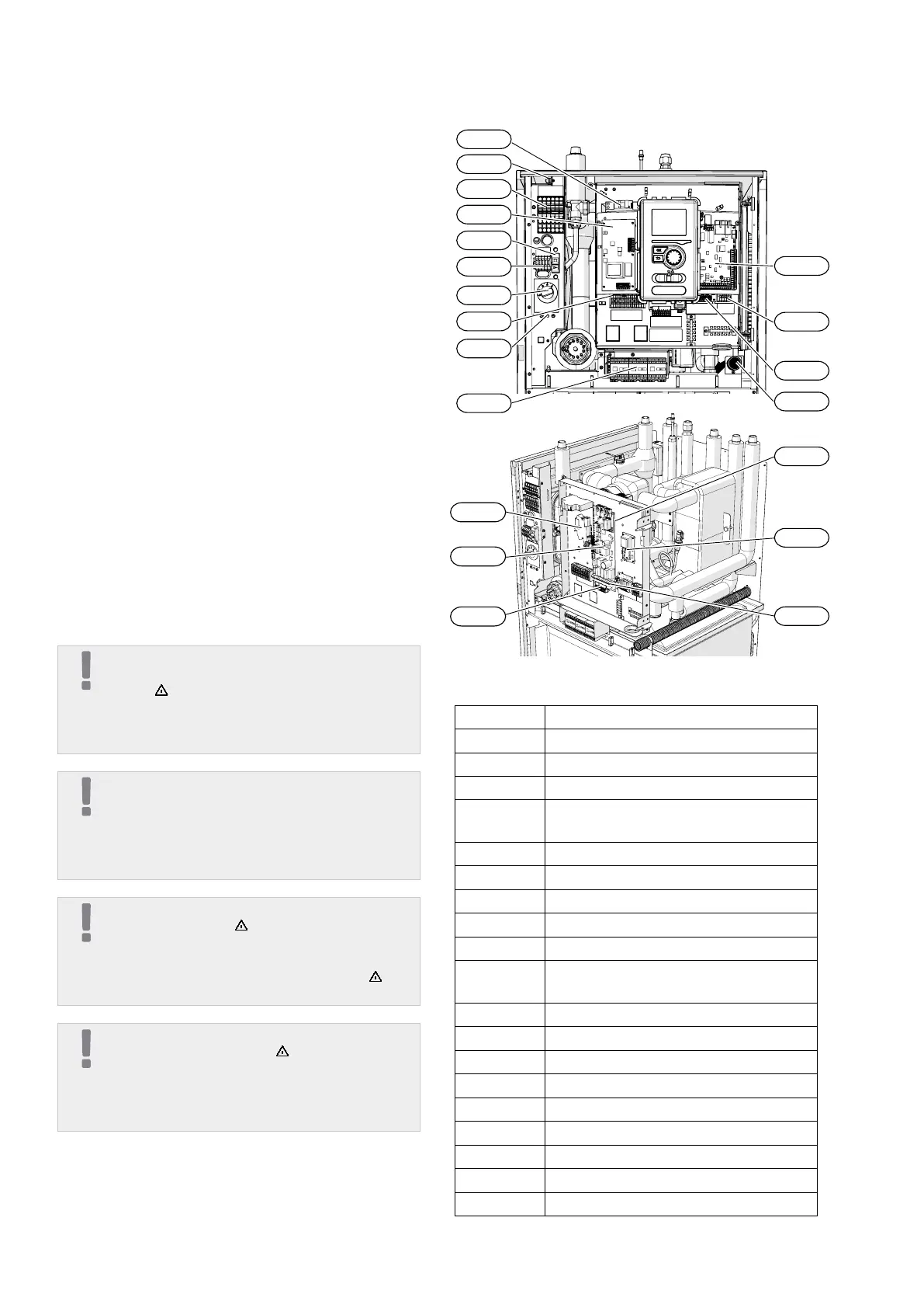
X10
UB1
BT30
X1
FD1
FA2
X0
FA1
K1A-K3A
AA23
AA3
UB2
X2
AA7
AA27
AA8
AA2:X4
AA2:X15
AA2
K2
X0 Terminal block - 400V~/230V~
X1 Terminal block - 230V~
X2 Terminal block - 230V~
X10 Terminal block - 230V~
FA1
Miniature circuit breaker
(for the indoor unit)
K1A-K3A Immersion heater contactors
BT30 Standby mode thermostat
AA3 Sensor board
AA23 Communication board
AA7 Relay board
FA2
AMS outdoor unit miniature circuit
breaker
FD1 Thermal circuit breaker
UB1 Cable grommet
UB2 Cable grommet
K2 Alarm relay
AA2 Main board
AA2:X15 Terminal block - low voltage
AA2:X4 Terminal block - low voltage
AA8 Titanium anode board
AA27 Relay board
 Loading...