69NIBE BA-SVM 10-200
HYDRAULIC CONNECTION
ELECTRICAL CONNECTION
The KVR 10 accessory is used to safely drain off most
of the condensate from the air/water heat pump to a
frost-free collection point.
For information on hydraulic connection of the KVR 10
accessory, see the instructions for the KVR accessory.
Length
(m)
P
tot
(W) Fuse (F3) Part no.
1 15 T100mA/250V 718 085
3 45 T250mA/250V 518 900*
6 90 T500mA/250V 718 086
*Fitted at the factory
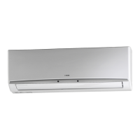
Plates to be punched-out
Residual-current device RCD
In order to connect the electric KVR accessory:
1. Open the control panel and punch-out the
notched plates in the control panel casing under
the residual-current device.
Section 12 | Accessories
Connecting the KVR accessory
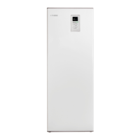
2. Attach the residual-current device RCD.
3. Use fuse (F3) depending on the length of the
KVR cable in accordance with the below table.
F3
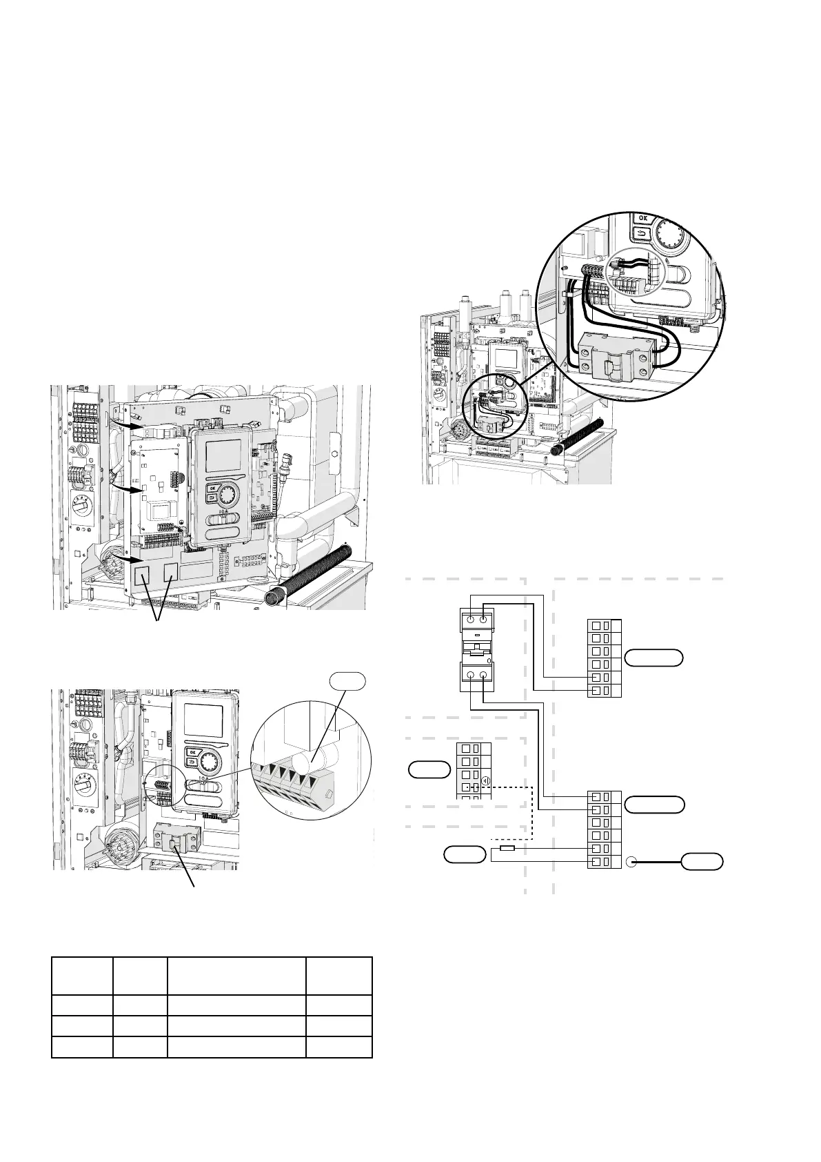
4. Connect a residual-current device to terminal
AA2-X1 under terminal block 5(N) and 6(L).
5 642 31
21
5 642 31
KVR
Wyłącznik
różnicowoprądowy RCD
10
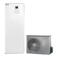
BA-SVM 10-200
BA-SVM 10-200
EB14
Zewnętrzny kabel
grzejny
AA23-X1
X1
AA2-X1
F3
PE
PE
N
N
N
L
L
L
5. Connect a residual-current device to terminal
AA23-X1 to terminal blocks 1(L) and 2(N).
6. Connect an external heating cable (EB14) to termi-
nal AA23-X1 to terminal blocks: 4 (PE), 5 (N), 6 (L).
Residual-current
device RCD
External heating
cable
 Loading...