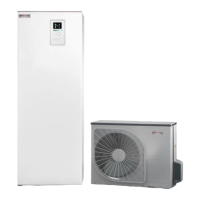
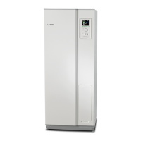
77NIBE BA-SVM 10-200
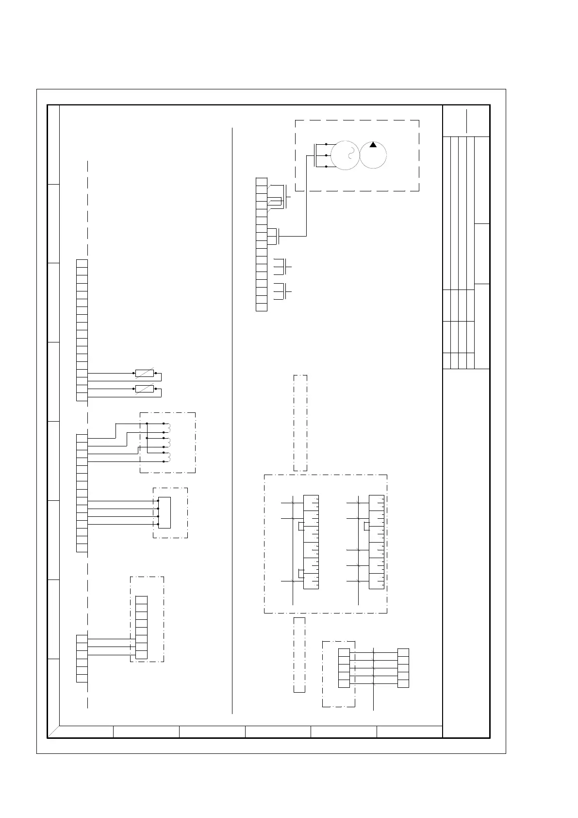
Electrical wiring diagrams
DATE
NEXT SHEET
SHEET
CHANGESNAMEREV.
Drawing no
External connection
1
Drawn by Date
A
1 2 3 4 5 6 7 8
B
C
D
E
F
2
A
B
GND
1234567891011121314
+AA3-X4
15
+12VDC
+AA3-X6
1 2 3 4 5 6 7 8 9 10 11 12 13 14 15 16 17 18
+AA23-X4
1 2 3 4 5 6
GND
B
A
+Next Accesory Card -AA5-X4
1 2 3 4 5 6 7 8
INPUTS AND COMMUNICATION
-E6
RMU40/SM40
POWER
+AA2-X4
1
PE
2 3 4 5
PE
6
N
7
-K2
8
L
9
PE
10
N
11
-K3
12
PE
M
1
-GP10
L
PE
N
EXT. CIRC PUMP
=OPTION
-BE3
-BE2
-BE1
LOAD MONITOR
A
B
GND
A
B
GND
29681
;PWM 1/GND
;PWM 1/PWM
-BT1
-BT50
OUTSIDE
ROOM
/3.3C
/5.5D /4.4B /4.4B
;PWM 2/GND
;PWM 2/PWM
-BT25
-BT6
-AU X1
-AU X2
-AU X3
-BT7
-BT71
-QN10
-GP12
N
K1
L
/3.5E
=OPTION
=OPTION
=OPTION
/5.7E
/4.5A
/4.4A
/3.3F /3.5F
/4.3B
/4.3B
L1 L2 L3 N N PE
5G2.5mm
L1 L2 L3 N N PE
3G10mm
400V 3NAC 50Hz
230V 1AC 50Hz
SUPPLY VOLTAGE
-X0
/8.2A
32PENL
5G2.5mm
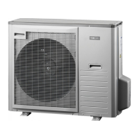
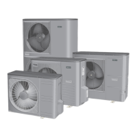
AMS10
/8.1C
-X10
Bridge B02 only for 230V 1AC 50Hz
Optional: remove the brigde B01 to separate
electrical heaters, e.g. with additional RCD
B01B02
B01
Brown
Black
Grey
Blue
Y/g
Brown
Blue
Y/g
32PENL
-TB
2
2
2
13
N
14
L
15
-K4:CO
16
-K4:NO
17
-K4:NC
022
-QN12
/3.6F
Section 13 | Technical data
 Loading...