8 PELLUX 100/20 TOUCH
PELLUX 100/30 TOUCH
EN
Operator Panel
Use of a Different Type of Container
Connect sensors and actuators to the control panel,
necessary for the boiler operation, as required. The
connection is made via CAN-bus communication
modules, which enable the installation of additional
accessories, such as:
• up to 4 heating circuits,
• 1 circuit for preparation of domestic hot water (DHW),
• Buffet tank,
• solar heating system,
• Lambda. probe,
• Internet module,
• room temperature sensor,
• outdoor temperature sensor.
The control panel is connected to the CAN-bus module
and power supply as shown in the gure below.
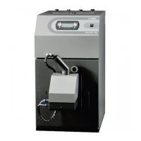
The PBMAX burner is to be mounted in the boiler door.
It should be secured using the supplied knobs. After
mounting the burner, ensure that it adheres tightly to
the boiler door, and then connect the HV and LV ca-
bles to the sockets on the left side of the burner.
The container should have a cover protecting the pel-
lets against moisture and the feeder mechanical com-
ponents against possible physical damage (e.g. due
to the penetration of a hard object that could damage
the feeder.)
The pellet feeder supplies the burner with fuel from an
external hopper. The screw feeder should be mounted
at an angle of 45 +/- 5 °. The feeding screw applied
should supply pellets in the amount of 10-11kg/h for
Pellux 100/20 and 12-13 kg/h for Pellux 100/30 during
continuous operation.
L
H
GND
+12V
GND
CAN
+12V
For the diagram of the controller block connection,
see Section 9. Wiring Diagrams.
IMPORTANT
Connections should be made with the unit disconnect-
ed from the mains. It should be performed by a person
with appropriate certicates in this regard.
IMPORTANT
Use a self-extinguishing corrugated pipe (included) to
connect the burner to the pellet feeder. The use of other
charging ducts is not allowed.
PBMAX Burner Installation
Pellet Hopper and Feeder
CAUTION
The burner’s safety circuit alarm can be activated if the
burner is not properly installed.
TIP
The amount of fuel fed may differ from the given val-
ues, depending on the type of pellets or the amount of
fuel in the pellet hopper.
CAUTION
We recommend disconnection of the feeder tube from
the burner and the cables before each opening of the
boiler door
IMPORTANT
The manufacturer shall not be held responsible for the
failure of the unit and the poor combustion process re-
sulting from the use of the wrong fuel tank.
LE K
Feeder
pipe cap
Hose clamp
HV connection
LV connection
The pellet hopper and feeder are available as acces-
sories:
• ZP350 (300L – approx. 200kg) + PP12/PPL 12 set
• ZP600 (500I- approx. 330kg) + PP15/PPL 15 set
Section 4 | Location and Installation

 Loading...