Connecting the brine side
■
Insulate all indoor brine pipes against condensation.
■
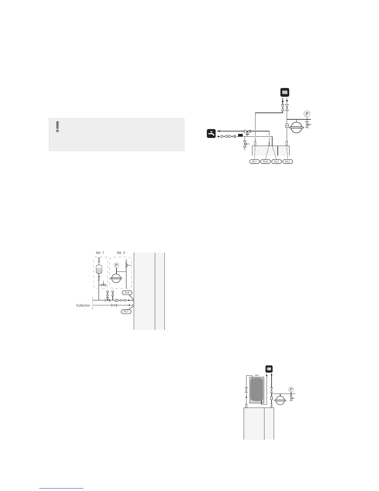
The level vessel must be installed at the highest point
in the brine system, on the incoming pipe before the
brine pump (Alt. 1).
If the level vessel cannot be placed at the highest point,
an expansion vessel must be used (Alt. 2).
NOTE
Note that condensation may drip from the level
vessel. Position the vessel so that this does not
harm other equipment.
■
Details of the antifreeze used must be shown on the
level vessel.
■
Install the enclosed safety valve under the level vessel
as illustrated. The entire length of the overflow water
pipe from the safety valve must be inclined to prevent
water pockets and must also be frost-free.
■
Install shut off valves as close to the heat pump as
possible.
■
Fit the supplied particle filter on the incoming pipe.
In the case of connection to an open groundwater sys-
tem, an intermediate frost-protected circuit must be
provided, because of the risk of dirt and freezing in the
evaporator. This requires an extra heat exchanger.
Collector
Alt. 1 Alt. 2
XL6
XL7
Heating medium side
Connecting the climate system
A climate system is a system that regulates indoor com-
fort with the help of the control system in F1226 and for
example radiators, underfloor heating/cooling, fan
convectors etc.
■
Install all required safety devices, shut-off valves (as
close to the heat pump as possible), and supplied
particle filter.
■
The safety valve must have a maximum 0.25 MPa (2.5
bar) opening pressure and be installed on the heating
medium return as illustrated. The entire length of the
overflow water pipe from the safety valves must be
inclined to prevent water pockets and must also be
frost proof.
■
When connecting to a system with thermostats on all
radiators, a relief valve must be fitted, or some of the
thermostats must be removed to ensure sufficient flow.
Water heater
Connecting the hot water heater
■
The hot water heater in the heat pump must be sup-
plied with necessary set of valves.
■
The mixing valve must be installed if the setting is
changed so that the temperature can exceed 60 °C.
■
The setting for hot water is made in menu 5.1.1.
■
The safety valve must have a maximum opening pres-
sure of 1.0 MPa (10.0 bar) and be installed on the in-
coming domestic water line as illustrated. The entire
length of the overflow water pipe from the safety valve
must be inclined to prevent water pockets and must
also be frost-free.
Docking alternatives
F1226 can be connected in several different ways, some
of which are shown below.
Further option information is available at www.nibe.eu
and in the respective assembly instructions for the ac-
cessories used. See page 47 for a list of the accessories
that can be used with F1226.
Buffer vessel
If the climate system volume is too small for the heat
pump output, the radiator system can be supplemented
with a buffer vessel, for example NIBE UKV.
15Chapter 4 | Pipe connectionsNIBE F1226
 Loading...


