Service actions
NOTE
Servicing should only be carried out by persons
with the necessary expertise.
When replacing components on F1226 only re-
placement parts from NIBE may be used.
Emergency mode
NOTE
The switch (SF1) must not be moved to "" or
" " until F1226 has been filled with water.
Component parts in the product can be dam-
aged.
Emergency mode is used in event of operational interfer-
ence and in conjunction with service. Hot water is not
produced in emergency mode.
Emergency mode is activated by setting switch (SF1) in
mode " ". This means that:
■
The status lamp illuminates yellow.
■
The display is not lit and the control computer is not
connected.
■
The temperature at the immersion heater is controlled
by the thermostat (FD1-BT30). It can be set either to
35 or 45 °C.
■
The compressor and the brine system are off and only
the heating medium pump and the electric additional
heat are active. The additional heat power in emer-
gency mode is set in the immersion heater board
(AA1). See page 21 for instructions.
Draining the water heater
The siphon principle is used to empty the hot water
heater. This can be done either via the drain valve on the
incoming cold water pipe or by inserting a hose into the
cold water connection.
Draining the climate system
In order to carry out service on the climate system, it may
be easier to drain the system first. This can be done in
different ways depending on what needs doing:
NOTE
There may be some hot water when draining
the heating medium side/climate system. There
is a risk of scalding.
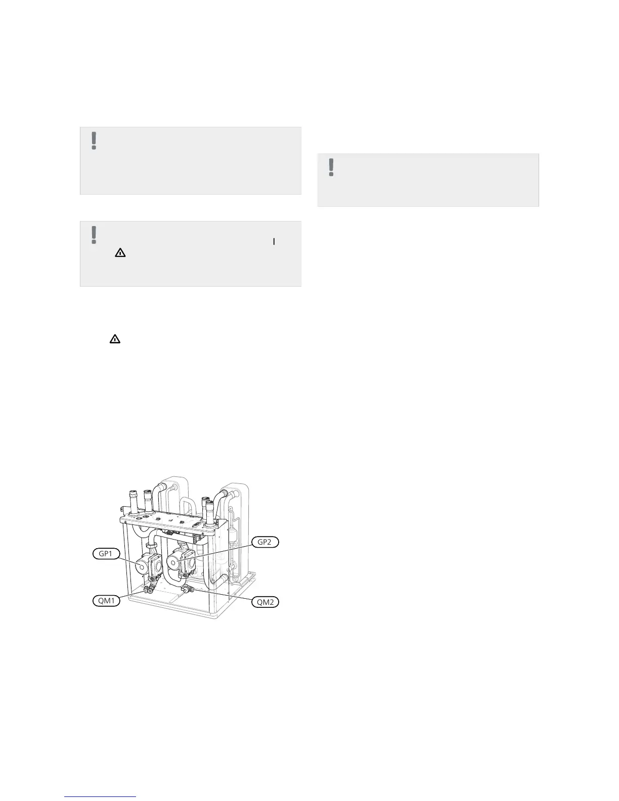
Draining the heating medium side in the cooling
module
If, for example, the heating medium pump requires re-
placing or the cooling module requires servicing, drain
the heating medium side as follows:
1.
Close the shut-off valves to heating medium side
(QM31) and (QM32).
2.
Connect a hose to the bleed valve (QM1) and open
the valve. Some liquid will run out.
3.
Air must get into the system for the remaining liquid
to run out. To let in air, slacken off the connection
slightly at the shut-off valve (QM32) that joins the
heat pump with the cooling module.
When the heating medium side is empty, the required
service can be carried out and/or replacement of any
components carried out.
Draining the heating medium system in the heat
pump
If F1226 requires servicing, drain the heating medium
side as follows:
1.
Close the shut-off valves outside the heat pump for
the heating medium side (return and flow line).
2.
Connect a hose to the bleed valve (QM1) and open
the valve. Some liquid will run out.
3.
Air must get into the system for the remaining liquid
to run out. To let in air, slacken off the connection
slightly at the shut-off valve that joins the heat pump
with the cooling module (XL2).
When the heating medium side is empty, the required
service can be carried out.
Draining the entire climate system
If the entire climate system requires draining, do this as
follows:
1.
Connect a hose to the bleed valve (QM1) and open
the valve. Some liquid will run out.
2.
Air must get into the system for the remaining liquid
to run out. To allow air in, unscrew the bleed screw
on the highest radiator in the house.
When the climate system is empty, the required service
can be carried out.
39Chapter 9 | ServiceNIBE F1226
9 Service
 Loading...


