EasyManuals Logo

Nibe F1226 series User Manual

Nibe F1226 series
68 pages
To Next Page IconTo Next Page
To Previous Page IconTo Previous Page
Page #7 background imageLoading...
Page #7 background image
Supplied components
O-rings
LEK
Safety valve
0.3 MPa (3 bar)
Outside sensor
22 28
Compression ring
couplings
6-8 kW
2 x (ø28 x G25)
2 x (ø22 x G20)
12 kW
4 x (ø28 x G25)
WILO
LEK
LEK
WILO
WILO
2,5(22)
H - 50 - 2,5
TUV-SV-97-525
WILO
LEK
LEK
WILO
WILO
2,5(22)
H - 50 - 2,5
TUV-SV-97-525
Particle filter
LEK
Level vessel
Location
The kit of supplied items is placed in packaging on top
of the heat pump.
Removing the covers
Front cover
1
2
LEK
LEK
LEK
LEK
LEK
LEK
1.
Remove the screws from the lower edge of the front
panel.
2.
Lift the panel out at the bottom edge and up.
Side covers
LEK
LEK
LEK
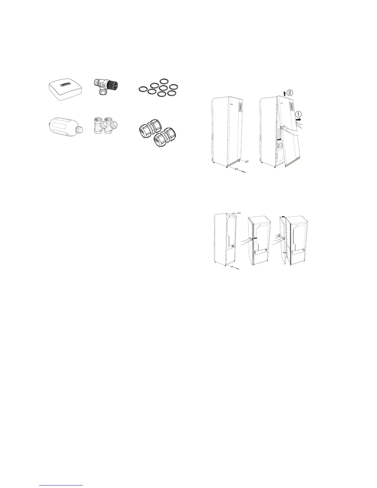
The side covers can be removed to facilitate the installa-
tion.
1.
Remove the screws from the upper and lower edges.
2.
Twist the cover slightly outward.
3.
Move the hatch outwards and backwards.
4.
Assembly takes place in the reverse order.
7Chapter 2 | Delivery and handlingNIBE F1226

Questions and Answers:

Question and Answer IconNeed help?

Do you have a question about the Nibe F1226 series and is the answer not in the manual?

Nibe F1226 series Specifications

General IconGeneral
TypeGround Source Heat Pump
RefrigerantR407C
Dimensions (HxWxD)1800 x 600 x 620 mm
Max Flow Temperature58°C
Integrated Hot Water TankYes
Control SystemNibe SMO 20
Power Supply400V 50Hz

Related product manuals