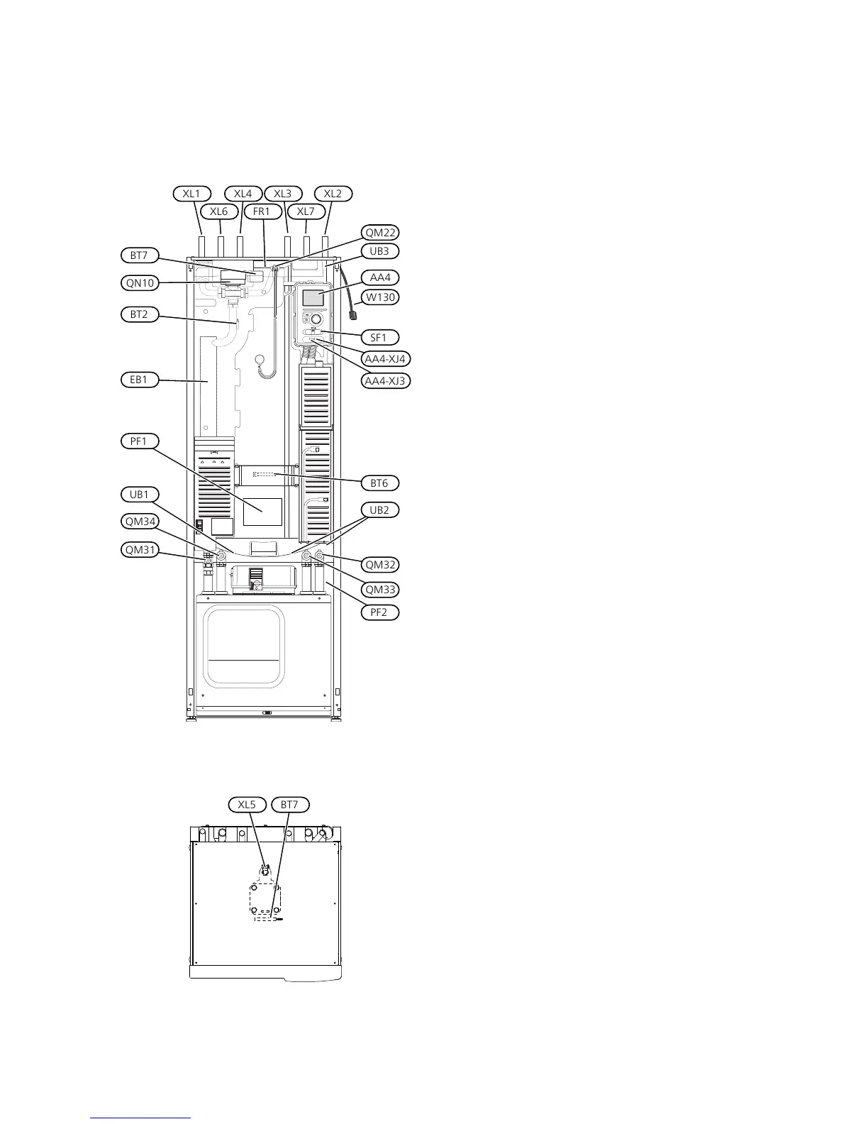
Pipe connections
Connection, heating medium flowXL1
Connection, heating medium returnXL2
Connection, cold waterXL3
Connection, hot waterXL4
Connection, HWC*XL5
Connection, brine inXL6
Connection, brine outXL7
* Only heat pumps with stainless steel vessel.
HVAC components
Venting, coilQM22
Shut-off valve, heating medium flowQM31
Shut off valve, heating medium returnQM32
Shut off valve, brine outQM33
Shut-off valve, brine inQM34
Shuttle valve, climate system/water heaterQN10
Sensors etc.
Outdoor temperature sensor*BT1
Temperature sensors, heating medium flowBT2
Temperature sensor, hot water chargingBT6
Temperature sensor, hot water topBT7
* Not illustrated
Electrical components
Display unitAA4
AA4-XJ3 USB socket
AA4-XJ4 Service outlet (No function)
Immersion heaterEB1
SwitchSF1
Miscellaneous
Rating platePF1
Type plate, cooling sectionPF2
Cable gland, incoming electricityUB1
Cable glandUB2
Cable gland, rear side, sensorUB3
Designations in component locations according to
standard IEC 81346-1 and 81346-2.
9Chapter 3 | The heat pump designNIBE F1226
3 The heat pump design
 Loading...


