EasyManuals Logo

Nibe F2040 Series User Manual

Nibe F2040 Series
92 pages
To Next Page IconTo Next Page
To Previous Page IconTo Previous Page
Page #26 background imageLoading...
Page #26 background image
Electrical components
Communication boardAA23
Fuse for external heating cable (250 mA), max
45 W.
AA23-F3
DIP switch, addressing of outdoor unitAA23-S3
Terminal block, KVRAA23-X1
Terminal block, communication from indoor
module
AA23-X4
Communication with TBAA23-X100
Compressor heaterEB10 (CH)
Drip tray heaterEB11 (DH)
Main fuse compressor unitF
FanGQ1 (FM01)
FanGQ2 (FM02)
Control boardPWB1
Inverter boardPWB2
Filter boardPWB3
EMC filter for inverterRF2
EMC filter for incoming supplyRF3
Terminal block, incoming supply and communic-
ation with board AA23
TB
Designations in component locations according to standard IEC 81346-2. Designations within brackets according to the supplier’s standard.
NIBE F2040Chapter 3 | The heat pump design26

Table of Contents

Questions and Answers:

Question and Answer IconNeed help?

Do you have a question about the Nibe F2040 Series and is the answer not in the manual?
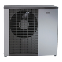
Nibe F2040 Series Specifications

General IconGeneral
SeriesF2040
RefrigerantR410A
COPUp to 5.0 (depending on model and operating conditions)
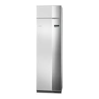
Sound Power Level Indoor UnitN/A (Requires separate indoor unit)
Operating Temperature Range Cooling+10°C to +43°C
Dimensions Indoor Unit (HxWxD)N/A (Requires separate indoor unit)
TypeAir Source Heat Pump

Related product manuals