Pipe connections 13
For the Installer
FIGHTER 310P
The enclosed expansion vessel (106) for tap water
shall be installed in the tap water circuit after the pres-
sure reduction valve.
Expansion vessel, tap water
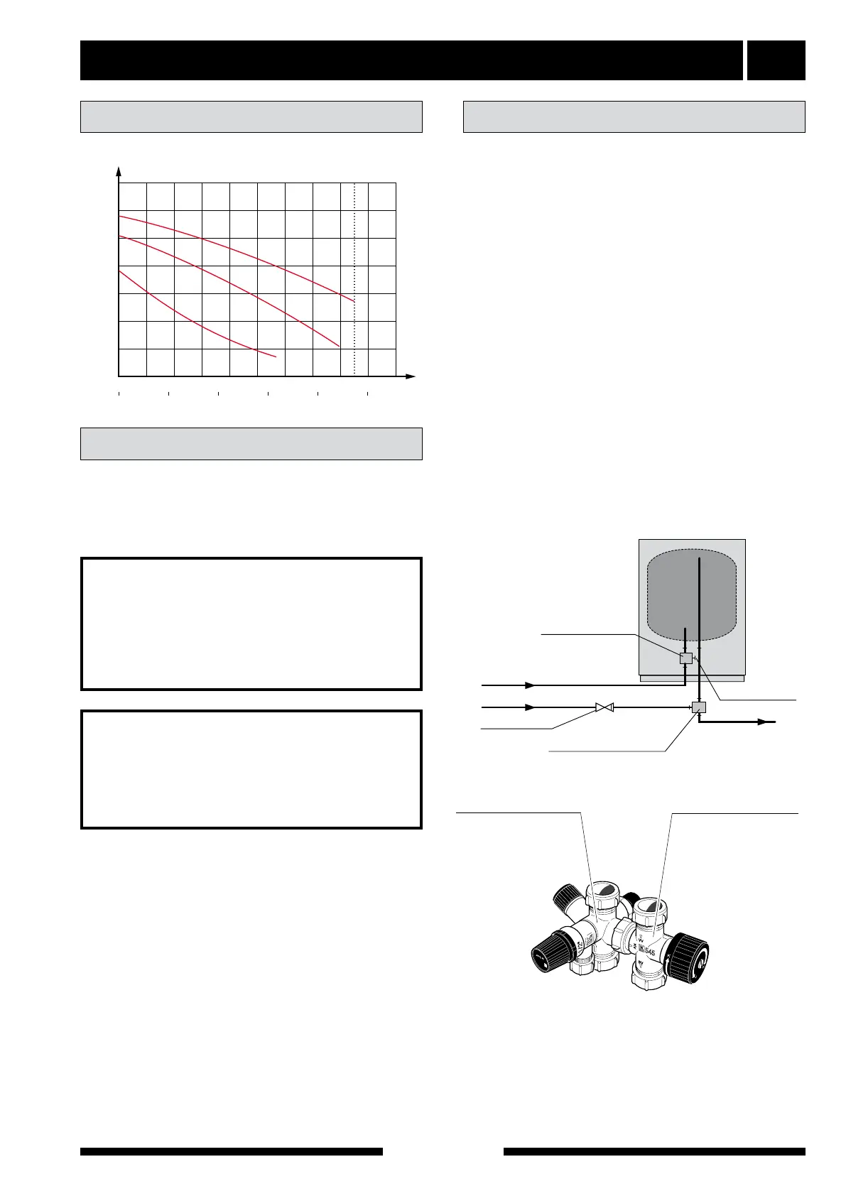
Pump and pressure drop diagrams
Pumpkapacitet
Flöde
Tillgängligt tryck, kPa
Internt tryckfall i panna
(inklusive armatur)
Tillgänglig pumpkapacitet
(pannans interntryckfall fråndraget)
3
2
1
0 500 1000
0
1500 2000
4
l/h
P
5
6
Interner Druckverlust in der Heizung
(einschließlich Armatur)
Zugängliche Pumpenkapazität
(interner Heizdruckverlust abgezogen)
3
2
1
kPa
kPa
60
50
40
30
20
10
0
mWs
l/s
0,50,40,30,20,10
Höchstmenge:1700 l/h
Höchstmenge:1700 l/h
3
2
1
0 500 1000
0
1500 2000
4
l/h
l/h
l/h
P
5
6
Internal pressure drop in boiler
(including fittings)
Available pump capacity
(less the internal pressure drop of the boiler)
3
2
1
wg
10
200
0
0
20
400
30
600
40
800
50
1000
60
1200
70
1400 1600 1800 2000
50
40
30
20
10
0
m
Flow
l/s
0,50,40,30,20,10
l/s
0,50,40,30,20,10
Max flow: 1700 l/h Max flow: 1700 l/h
Max flöde: 1700 l/h
l/s
0,50,40,30,20,10
Flow, l/h
Available pump capacity, kPa
10
200
0
0
20
400
30
600
40
800
50
1000
60
1200
70
1400 1600 1800 2000
Menge
Vorhandener Druck, kPa
10
200
0
0
20
400
30
600
40
800
50
1000
60
1200
70
1400 1600 1800 2000
Max flow
1700 l/h
Available pressure, kPA
Flow
Warning to the
installer!
This installation is subject to building
regulation approval, notify the Local
Authority of intention to install.
Warning to the
installer!
Use only manufacturer’s
recommended replacement parts.
Tap water connection
Hot and cold water are connected to pos (74) (hot
water) and (73) (cold water).
The attendant expansion vessel (107) must be con-
nected to the hot water system.
The heat pump should be supplemented with an elec-
tric water heater if a bubble pool or other significant
consumer of hot water is installed.
If the heater is equipped with a valve connection Ø of
15 mm, this should be replaced with an equivalent
(split) Ø 22 mm coupling.
Appropriate heaters are COMPACT 100-300 for floor-
mounting and EMINENT 35-100 for wall-mounting.
1. Split the valve coupling.
2. Attach the valve coupling section to the heater’s
incoming cold water.
3. Attach the mixing valve section to the heater’s out-
going hot water.
4. Plug the split on the valve coupling section.
LK 550/506/513 LK 545/506/513
LK 545/508/518 MMA MMA/LK 518 SYR
LK 506
LK 501
SOLE
LK 545/508/514 LK 545/508/514
utan vakuumventil
LK 550/Cu-rör/506//513 LK 540/512
LEK
LEK
LEK
LEK
LEK
LEK
0,9
MPa
LEK
LEK
LEK
LEK
LK 560/514
ARMATUR
LEK
LEK
LEK
ARMATUR
LEK
ARMATUR
Valve coupling section
Mixing valve section
KV
VV
VV
INK KV-ANSL
PROPPNING
KV
VV-BEREDARE
MED "DELAT"
VENTILKOPPEL
BACKVENTIL
Kv
Vv från värmepump
Vv
Proppas
Backventil
KV
VV
VV
INK KV-ANSL
PROPPNING
KV
VV-BEREDARE
MED "DELAT"
VENTILKOPPEL
BACKVENTIL
Ventilkoppel-del
Blandningsventil-del
Kv
Vv från värmepump
Vv
Backventil
Blandningsventil
ENDAST FÖR
DANMARK
Valve coupling section
Plugged
Non-return valve
Hw from heat pump
Cw
Hw
Mixing valve section