Service
FIGHTER 310P
For the Installer
24
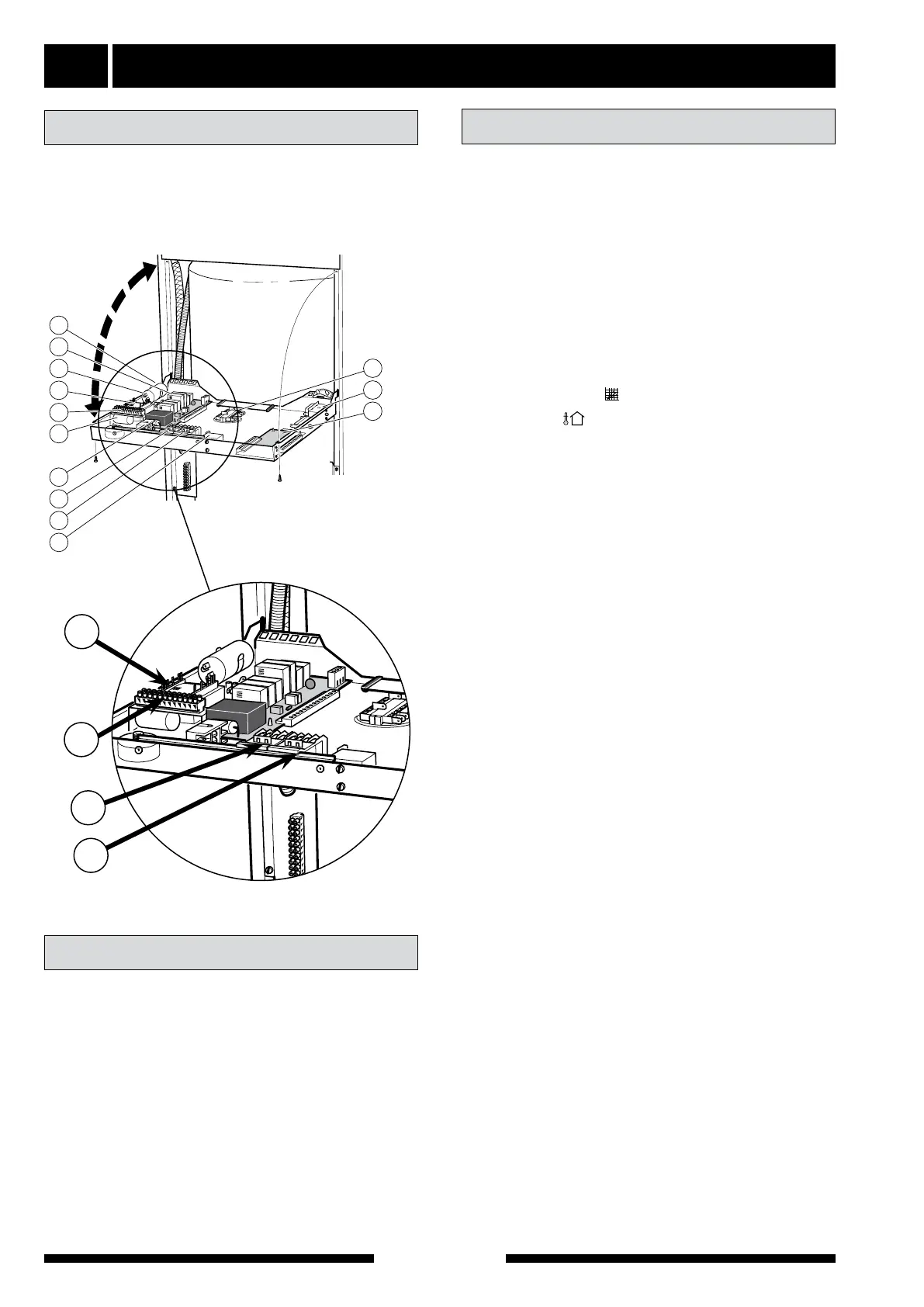
To lower the front panel, unscrew the two screws at
the top of the panel. The panel can then be lowered to
the horizontal position (where it rests on stops on
either side of the front panel).
Work on the refrigerant system must be done by
authorised personnel in accordance with the relevant
legislation on refrigerants, supplemented by additional
requirements for flammable gas, for example, product
knowledge as well as service instruction on gas sys-
tems with flammable gases.
Opening the front panel
Refrigerant system
LEK
LEK
34
29
6
107
10
3
67
8
57
54
22
7
28
LEK
LEK
34
29
6
107
10
3
67
8
57
54
22
7
28
54
22
67
10
01 Boiler temperature
Actual value
02 Supply temperature
Actual value
03 Outside temperature
Actual value
04 Evaporation temperature
Actual value.
05 Extract air temperature
Actual value.
06 Curve slope ( Heating curve selection)
07 Offset ( Heating curve offset)
08 Temperature, compressor sensor
Actual value.
09 No function
Shows – –
10 Calculated flow
Set point.
Service ducts
11 Deviation flow
Actual value
12 No function
13 No function
14 Operating mode
01 = Circulation pump in operation. Compres-
sor respective immersion heater is con-
nected if necessary.
02 = Circulation pump in operation. Compres-
sor is connected if necessary. Immersion
heater blocked.
03 = Immersion heater and circulation pump
blocked. Compressor is connected if nec-
essary.
15 Room sensor
Set point. Shows the set room temperature.
Shows – –
when the room sensor is not con-
nected.
16 Room sensor
Actual value. Shows the true room temperature.
Shows – –
when the room sensor is not con-
nected.
17– 21 No function
Channel description