Electrical circuit diagram
25
For the Installer
FIGHTER 310P
6.0 kW to 8.0 kW
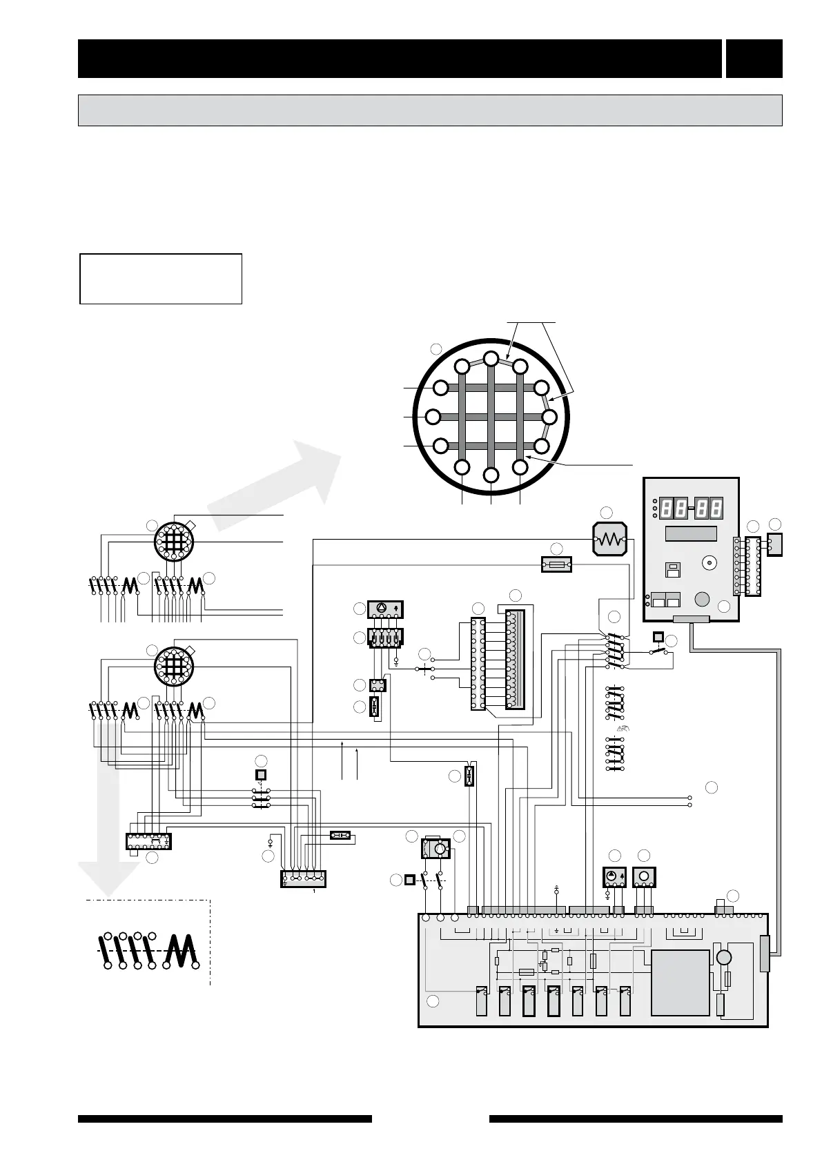
Move cable “67A1-12” from the parked position, posi-
tion “14” on contactor (67) to position “A1” on the same
contactor, see output option “8 kW”.
Contactor 10 controls step 1
Contactor 67 controls step 2
Changing the output
169
T
1
8,0 kW
3 x 1 kW
Läge R
7
10
67
T
6
9
8
3
M
19
4
16
57
20
36
1
25
3
4
6
7
8
9
10
12
13
14
15
16
17
18
19
20
21
22
23
24
26
27
28
29
30
31
32
33
34
11
2
1
T
Läge I
Läge 0
27
26
28
15
14
5
13
41
40
39
38
37
36
35
Re
1
Re
2
Re
3
Re
4
Re
5
Re
6
Re
7
29
~
~
–
+
230 V 12 V
B1
+–
C1
34
Brun
Blå
Svart
VR1
C2C3
F3
F1
F2
C4
L2
L1
5
2
1
3
4
P3
P1
P2
1 2 3 4 5 6 7 8
6,0 kW
1
Noll-bleck
Elementslinga
C
R
S
3 x 2 kW
M
B
C
D
E
F
G
H
I
J
K
L
10
67
10A1-10
67A1-12
A1A224614
13513
Kontaktormärkning
Gäller samtliga kontaktorer
6,0 kW Brun2,0 kW Vit
6,0 kW Brun0 kW Vit
11
NN3
Elektrisk matning
för effektvakt (tillbehör)
82
68
5 6 7 8 9 103 41 2
54
22
107
099
097
095
NL
white
brown
brown
white
brown
blue
black
Contactor marking
For all contactors
Pos 1
Power supply for load
monitor (accessories)
Pos 0
Element circuit
Neutral strip
Pos