Commissioning and adjusting
FIGHTER 310P
For the Installer
18
k.v.
v
.v.
Blaha
b
lah
a
o
ch anna
t
trams
Blaha
b
lah
a
och anna
t
trams
k.v.
v
.v
.
Blaha b
laha
o
c
h anna
t
trams
Blaha
blaha
o
ch annat
trams
2
1
bar
3
0 4
2
1
bar
3
0 4
LEK
LEK
6
25
55
56
39
18
40
38
31 32
94
1
88
86
30
37
Fram-
ledning
radiatorer
11
9
59
16
17
44
70
19
44
89
78
27
36
33
58
95
52
96
97
8
62
48
63
87
65
99
14
82
Åter-
ledning
radiatorer
k.v.v.v.
41
103 518071506615114974 73
84
98
108
85
53
7
109
145
107
42
61
t
trams
t
35
16
19
35
47
148
43
150
6
25
55
56
39
18
40
38
31 32
1
88
86
30
37
11
9
59
44
44
78
27
36
33
58
52
96
97
8
62
48
63
87
65
14
82
41
50
98
7
109
145
107
42
t
trams
t
148151149
49 15049
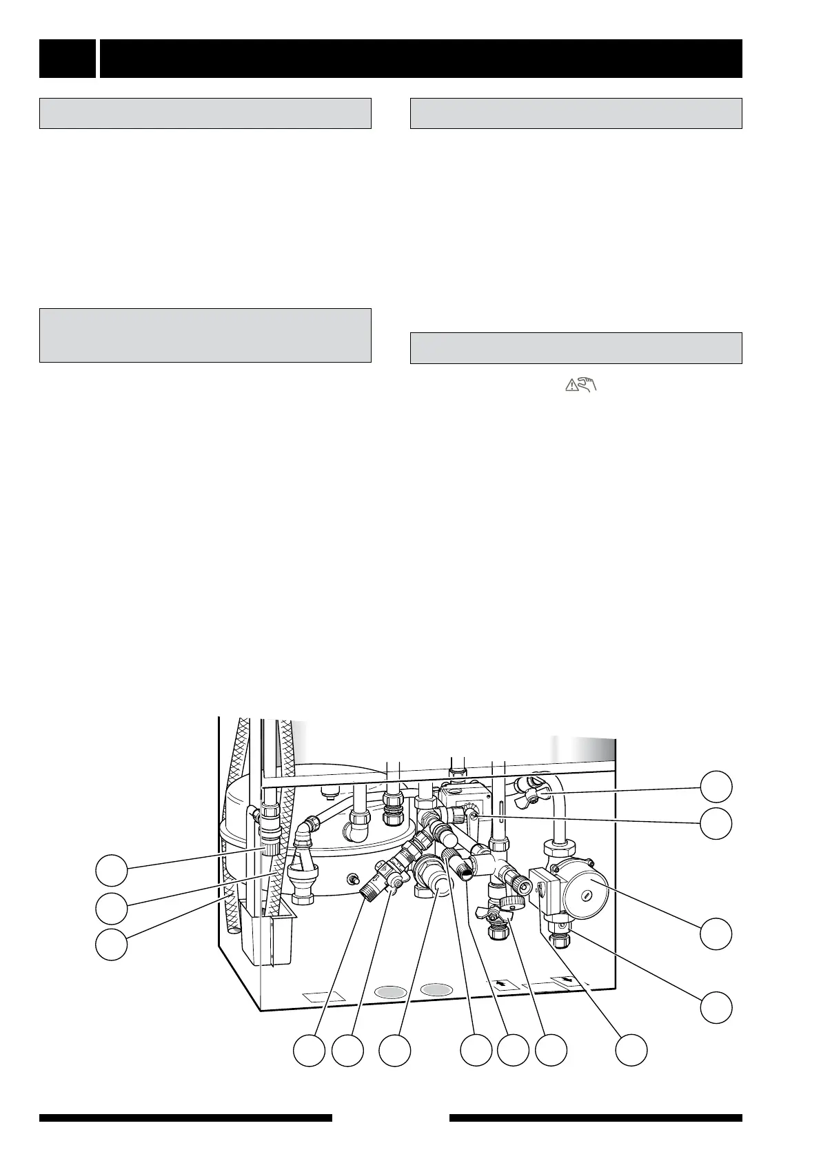
NOTE! The pipe from the container must be drained of
water before the air can be removed. This means that
the system is not necessarily vented, despite water
emerging from the safety valve (52) when it is opened
for the first time.
■ Vent the heat pump through safety valve (52). The
remainder of the heating system is vented by
means of each venting valve.
■ Keep topping up and venting until all air has been
removed and the pressure is correct.
■ Set the switch (8) to “
”. In this mode the elec-
tronics are disconnected, so the display window is
not lit. The thermostat (3) opens at 68 °C in this
mode.
■ Set the shunt (19) by hand (turn the adjuster screw
to manual mode and then turn the shunt lever to
the required position).
■ When the room temperature goes above 16 °C set
switch (8) to “1”. NOTE! The display may still not be
lit, this comes on automatically when the boiler
temperature has dropped a few degrees. The com-
pressor has a start delay of at least 20 minutes.
■ Reset the shunt (19) by hand (turn the adjuster
screw to “A”).
■ Set the dimensioned capacity (35) on the circula-
tion pump (16). See the section “Pipe connections”
“Pump and pressure drop diagram”. Make sure that
the switch is not in an intermediate position.
Check that the switch (8) is set to “0”.
Check that valves (44) and (50) are fully open and that
the temperature limiter (6) has not tripped (press the
button firmly).
Fill the condensation water hose (97) with a little water
to prevent it making a noise. This done by loosening
the hose which is located on the waste water pipe (98)
and pouring water in the end of the hose so a water
seal arises. Refit the hose.
Venting the heating system
Starting
Preparations
■ The water heater is filled by opening a hot water
tap. When water comes out of the hot water tap this
can be closed.
■ Connect enclosed flexible hose (147) between con-
nection (149) and connection (150) (the hose is
mounted at the unit when this is delivered). Open
filling valves (151) and (49). The boiler part of the
heat pump and the radiator system are now filled
with water.
■ After a while the pressure gauge (42) will show ris-
ing pressure. When the pressure reaches 2.5 (bar)
(approx. 25 mvp) a mixture of air and water starts
to emerge from the safety valve (52). The filling
valves (151) and (49) are then closed.
■ Turn the safety valve (52) until the boiler pressure
reaches the normal working range (0.5 - 1.5 bar).
■ When the filling procedure is finished the flexible
hose (147) shall be removed.
Filling the water heater
and the heating system